Xuberance Breaks the Mold with 3D Printed Furniture and Lifestyle Products

Xuberance 3D printed furniture - hero image
Hailing from Beijing, China, Xuberance is a product design firm that leverages 3D printing technology to create unique furniture pieces and accessories. By embracing BigRep’s large-scale 3D printers, Xuberance is writing a new design narrative that combines sustainability and unparalleled design freedom.

From steam-bending woodworking techniques in the 19th Century to injection molded plastics in the 20th Century, advances in production technologies have continually reframed the creative possibilities. Product designers are looking to innovate and push the boundaries of their craft with cutting-edge technologies that allow them to support their vision.

In the 21st Century, design firms such as Xuberance are proving that there is scope for an entirely new conversation - one that empowers the unbound imagination of the product designer thanks to 3D printing technology.

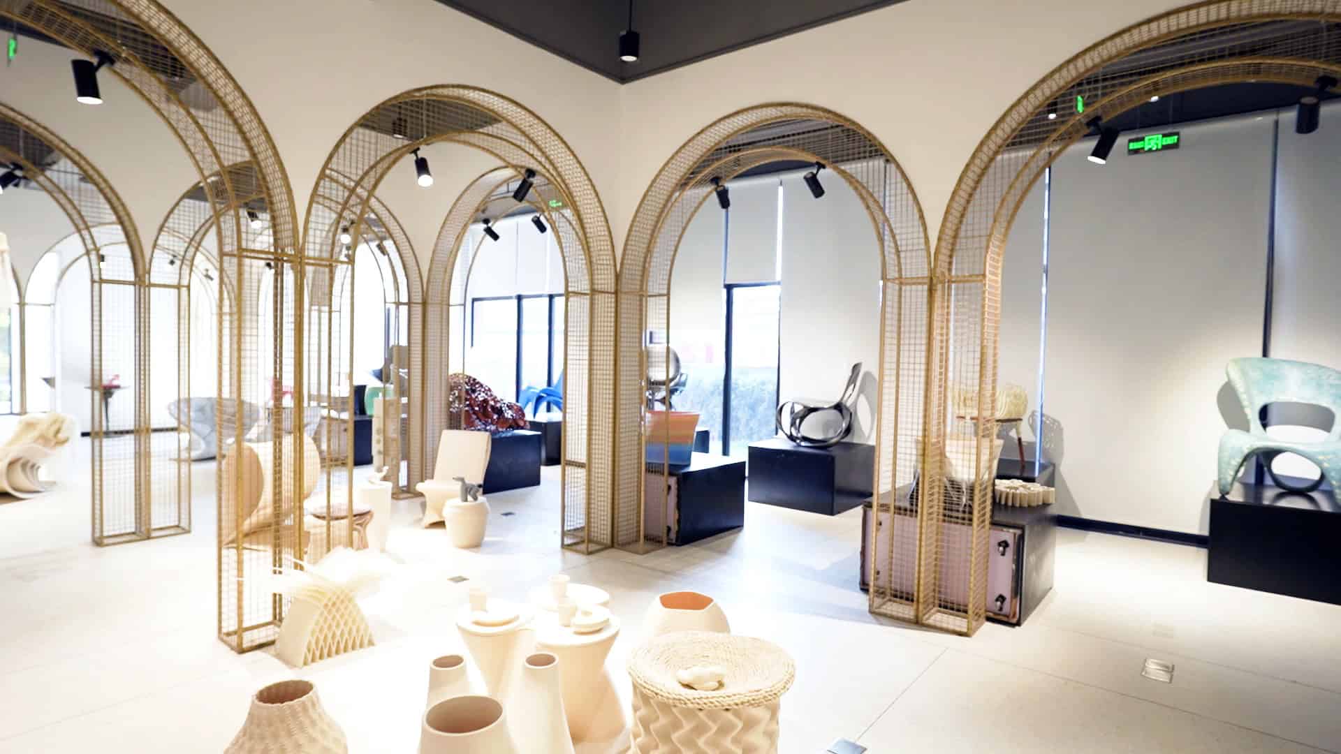
Xuberance is making complex, intricate, and lightweight structures made possible by 3D printing objects from digital designs. The design ranges from furniture pieces to wearable fashion accessories and has become a symbol of a new age of digital expression.

The Form is More Than Function

With products such as the 3D printed Cloud Lamp, a luminaire that garnered the team the prestigious SaloneSatellite Award at the Milan Design Week in 2015, Xuberance has developed a distinctive design language; a language inextricably bound to the digital process of 3D printing.

The resulting intricate, organic forms of its 3D printed products are so unique, that they are virtually impossible to reproduce with conventional production methods such as molds.

Xuberance 3D printed furniture - BigRep 3d printed chair

“3D printing forms the backbone of our entire design and production process,” comments Leira Wang, Managing Director of Xuberance.

“Our designers can fully translate their digital designs into physical products using 3D printers such as BigRep’s. It offers unparalleled design freedom while pushing the boundaries of what’s technically possible.”

Xuberance_13

Large Scale Printing Creates Unique Design Possibilities

Although 3D printing was traditionally utilized by manufacturers to produce specific parts, Xuberance was one of the pioneers to embrace the medium as its primary tool to produce entire products from the ground up.

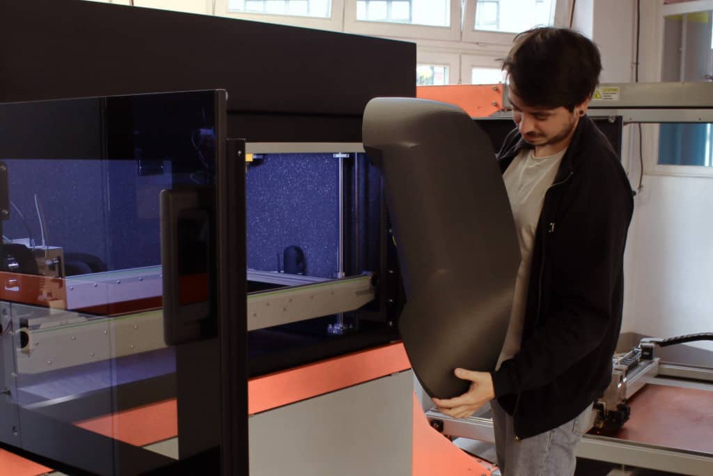
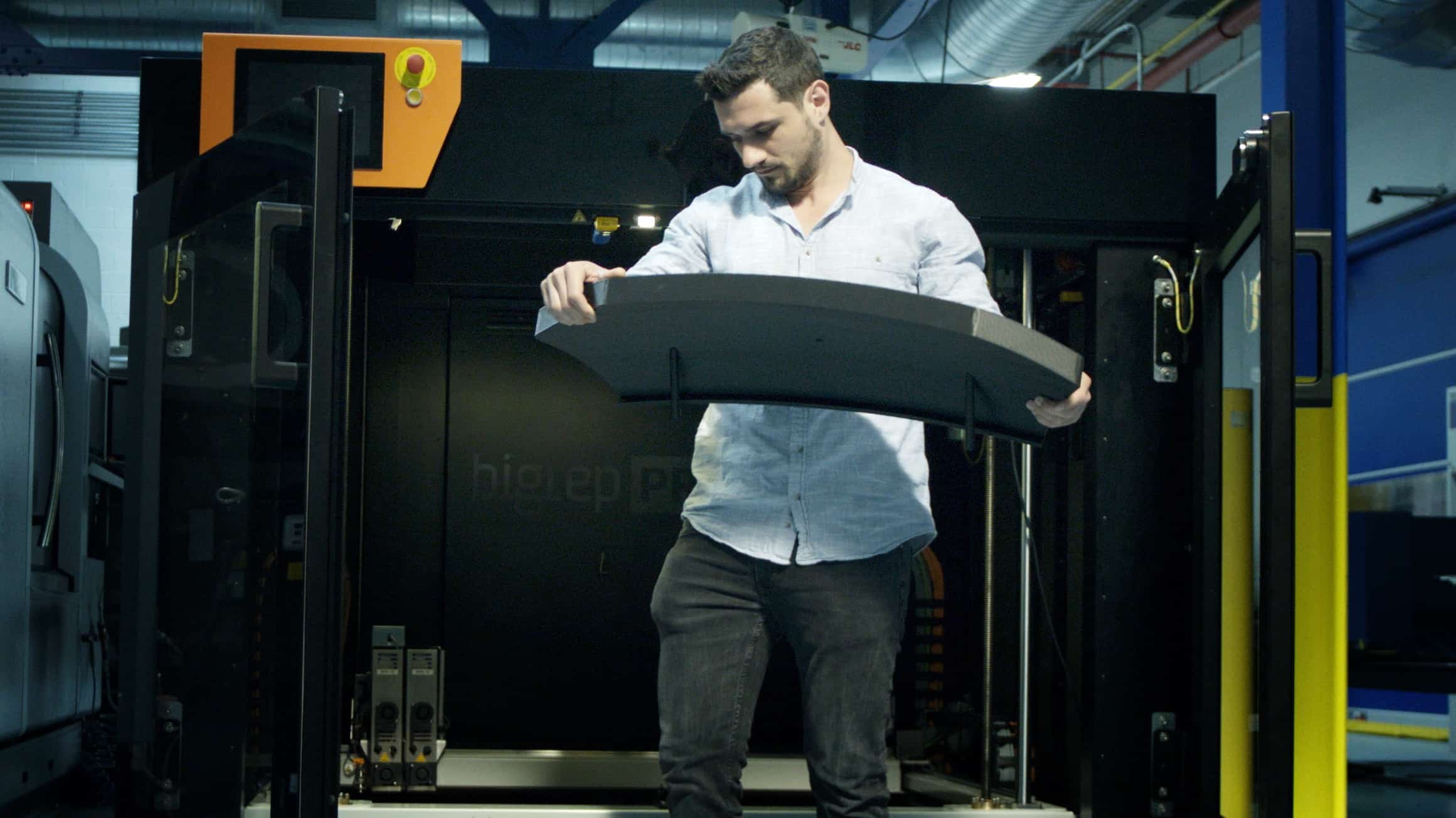
Having the ability to print larger single products such as chairs and stools with 3D printers such as BigRep’s ONE and STUDIO has enabled Xuberance to focus on building its product design niche.

The resulting products are not only strong, durable, and lightweight, but also unique in their form.

“Large-scale printing has had a transformative effect upon our overall ability to create distinctive designs,” continues Wang. “The BigRep large scale printers are instrumental in this, and unlock new possibilities by reducing time and costs.”

Xuberance_12

As evident with Xuberance products such as the Madame Butterfly chair - a single-piece 3D printed chair consisting of ethereal, organic, and intricately printed patterns, BigRep’s 3D printers allow the production of larger objects while retaining the intricate design.

“BigRep's dual extrusion printing offers a crushing advantage with its super accurate printing quality. We’re now able to faithfully translate our designer’s compositions into finished Xuberance products without losing any of the intricacies of the original design.”

says Wang.

Xuberance_11

Responding to Customer Demand

Unlike traditional manufacturing, where modifications require mold changes or adjustments to tooling, Xuberance has built its business around the flexibility of 3D printing, which allows for quick iterations to final product designs.

Not only has this allowed the team to eliminate the time and cost associated with physical adjustments in texture, structure, or color gradients can also be quickly executed depending on the customer’s requirements.

Xuberance_2

3D Printing in a Circular Economy

Product design and furniture industries have been plagued by non-sustainable practices, especially with nonbiodegradable plastics and other materials. But Xuberance is proving that 3D printed products have earned their place within the circular economy with their choice of materials.

With BigRep’s open material system, Xuberance can select the appropriate materials according to the requirements of each design, and set up printing parameters for each geometric model.

Xuberance_7

In addition to citing BigRep’s PRO HT and ASA filaments as exceptional with regards to their material composition and heat resistance qualities, Wang also highlighted the importance of their biodegradability in underlining the ethos of the company.

A Future Filled with 3D-Printed Possibilities

By embracing 3D printing technology, Xuberance has proven that it’s possible to create stunning, customized products whilst paving the way for a more sustainable future in design. Key to achieving this are the BigRep large format printers, which Wang believes are fundamental to achieving the company’s vision.

Xuberance_6

"There is an ancient Chinese saying," concludes Wang, "' When brothers are united in purpose, their strength can cut through metal.' We believe in the future of large-scale printing, and we will work together with BigRep to achieve this greater development."

As Xuberance continues to explore the unprecedented creative possibilities of 3D printing, its designers are forging a radical new language formed around the desire to celebrate form and organic beauty.

This approach echoes a historical truth: form isn't dictated by function, but rather, by the tools and technology available to the designer at any given time. With the tools of 3D printing at its disposal, Xuberance is at the very cusp of redefining the possibilities of product design.

Want to Learn More about 3D Printing Bespoke Furniture?

Download the eBook, RH-Engineering & manoFigura 3D Print Luxury Furniture.

Find out how RH-Engineering and manoFigura design and create custom furnishings. Deep dive into their breakthrough product, the Magna Patero Ortus – a 3D-printed end-use sink.

Read this additive manufacturing case study to learn:

  • How businesses are manufacturing custom products with 3D printing
  • Why additive manufacturing is the perfect solution for custom and low-volume production
  • How large-format 3D printers unlock creativity and opportunity
  • Unique post-processing systems for end-use products

HOW RH-ENGINEERING & MANOFIGURA 3D PRINT LUXURY FURNITURE

About the author:

Patrick McCumiskey <a style="color: #0077b5" href="https://de.linkedin.com/in/patrick-mccumiskey-b41a2699" target="_blank" rel="noopener"><i class="fab fa-linkedin"></i></a>

Patrick McCumiskey

Author

Patrick has over a decade’s worth of experience writing about design and technology. After first encountering 3D printing on a project while studying a Masters Degree in design, he’s taken a keen interest in the development of 3D printing and its impact on the world of design and tech.

3D Printing Accelerates Innovation in China’s Commercial Vehicle Industry

Large 3D Printing Transforms Commercial Vehicle Industry

China's commercial vehicle market accounts for over 40% of total global sales. Playing a key role in China’s success is the industry’s willingness to adopt new disruptive technologies like industrial 3D printing to pave the way for a new generation of production in custom commercial vehicle manufacturers such as CNHTC.

At the helm of this transformation is Dr. Dong, a visionary engineer, who established one of China’s largest 3D printing centers within CNHTC, the third-largest commercial vehicle manufacturer in the country.

With Chinese domestic demand for commercial vehicles projected to increase 10% year on year by 2028, Dr. Dong and his team could no longer exclusively rely on traditional manufacturing methods to meet the constantly evolving industry’s requirements.

Thanks to industrial 3D printing, the company has been able to advance prototyping and production processes for its heavy-duty trucks, haulage, and transport vehicles.

Embracing the Open 3D Printing System

Dr. Dong's approach to 3D printing is centered around being able to explore new applications and materials that are fundamental while innovating with the technology. While some of the 3D printer providers only sell closed material and software systems which limit application freedom, industrial 3D printers, like BigRep’s, are open for innovation. Being able to use any 3D print filament and software enabled CNHTC’s designers and engineers to leverage any technically compatible material.

It also helped CNHTC save costs as typically when companies are locked to the 3D printer provider’s materials, they’d have to forgo applications, outsource the print, or if the part warrants the investment, buy a new 3D printer that supports the material. CNHTC also had a better return on investment as they discovered the machine could be used for new applications with other materials.

CNHTC -Dr. Dong with a 3D print

Dr. Dong explains,

Having an open-source 3D printer like the BigRep PRO is vital for our workflow. Open-source materials not only reduce production costs, they allow us to explore diverse material possibilities to achieve any number of desired outcomes

Cost and Time Savings with Rapid Prototyping

CNHTC's traditional reliance on CNC machining and milling for prototyping translated to lengthy testing and iteration phases, often taking weeks. As a result, this slow process hurt the company’s ability to innovate within its design team.

Since we’ve adopted 3D printing into our day-to-day work processes, we’ve witnessed a remarkable 50% reduction in both time and cost compared to traditional manufacturing methods for our projects to date.”

says Dr. Dong.

CNHTC 3D printed parts with the BigRep PRO

With the introduction of 3D printing, CNHTC’s workflow has undergone a total transformation. Now it takes just a few days, not weeks, for Dr. Dong and his team to turn digital designs into functional parts. "3D printing has enabled our designers and engineers to perform iterative optimizations with much faster turnaround times." Say Dr. Dong "While bypassing the mold-making stage entirely, we can directly 3D print structures that could not be created by the traditional processes.”

This kind of efficiency has allowed for the introduction of faster iteration and feedback cycles, ultimately allowing the design team to create products more in line with current market demands.

Large-Scale 3D Printing for Heavy-Duty Trucks

While previous generations and some of the current 3D printers have a smaller build limiting the size of the parts, Dr. Dong and his team have embraced industrial 3D printing with the BigRep PRO to produce large singular parts suitably sized for custom commercial trucks.

Following the same path as European commercial vehicle specialists like Zoeller Kipper, large 3D-printed parts such as customized panels and covers are being integrated as end-use components in CNHTC’s commercial trucks.

The BigRep PRO at the 3D printing CNHTC center

The high level of precision and dimensional accuracy in the large, robust prints meet CNHTC’s need for high-quality functional end-use parts. Printing sizable parts helps CNHTC eliminate the time-consuming and manual process of assembling smaller parts that might have errors in assembly.

He elaborates, "The quality of the larger printed parts makes it easy to integrate them directly into our vehicles. This not only increases production efficiency but also allows us to respond better to the demands of the market."

The Future of 3D Printing in Custom  Commercial Vehicles

"What excites me most about the future is the possibility of using 3D printing to create more batches of end-use parts that can be directly used for manufacturing.” comments Dr. Dong.

The future of heavy duty vehicle customization with 3D printing for CNHTC

Confident in this blueprint for the future, Dr. Dong sees even greater potential for integrating 3D-printed parts directly into CNHTC’s production facilities. He concludes,

The application of 3D printing in commercial vehicles is one of the most significant technological events to have occurred in the automotive industry. The rules of the game have changed for the better, and we are using this to our full advantage

Want to Learn More about 3D Printing for Emergency and Commercial Vehicles?

Register to watch the webinar, Improve Time to Market for Custom Commercial Vehicles

Learn how large-format 3D printers give companies the flexibility and versatility to iterate fast, produce faster, and get to market faster, all while reacting to challenging customer requirements on short notice.

REGISTER FOR THIS WEBINAR TO LEARN ABOUT

  • Large-format 3D printing and customer applications
  • How BigRep is supporting the trucking industry
  • Customer success stories from prototyping to end use parts
  • Benchmark breakdown

IMPROVE TIME TO MARKET FOR CUSTOM COMMERCIAL VEHICLES

About the author:

Patrick McCumiskey <a style="color: #0077b5" href="https://de.linkedin.com/in/patrick-mccumiskey-b41a2699" target="_blank" rel="noopener"><i class="fab fa-linkedin"></i></a>

Patrick McCumiskey

Author

Patrick has over a decade’s worth of experience writing about design and technology. After first encountering 3D printing on a project while studying a Masters Degree in design, he’s taken a keen interest in the development of 3D printing and its impact on the world of design and tech.

How To Pick A 3D Scanner For The Automotive Aftermarket

3D scanner for car customization - feature image

In the realm of aftermarket car customization, automotive 3D scanners can be the overlooked workhorse that brings physical objects into the virtual space. While some car components might have readily available 3D models, designing individualized or original 3D prints needs 3D scanners to recreate an object’s geometry accurately in a simulated environment. The 3D scanner does this by capturing millions of data points from all angles of the part and in minutes you have a complete digital clone of it. This virtual version serves as a three-dimensional test bed to build and iterate concepts swiftly before going into prototyping and production.

3D Scanner car customization


Typically, large-format 3D printers come into the picture when printing car parts or bespoke components like dashboards, consoles, and door panels. Coupled with 3D scanning technology, you get visually aesthetic and highly functional parts. 3D scans seamlessly integrate with large-format 3D printers and streamline the process from the outset saving time, effort and money, resulting in exceptional print quality with fewer failed prints.

So How Do You Pick A 3D Scanner That’s A Good Fit For Your Workshop?

To get to the bottom of this, we will explore:

1. Why Is 3D Scanning Important?

3D scanning offers endless possibilities for customization with which you can design and produce components quickly with a high level of precision and accuracy.

Quality Control

The virtual 3D model can be evaluated to make sure every aspect of the part is precisely measured and is within the specified tolerances.

Reverse Engineering

A 3D scanner captures complex geometries with high-quality CAD files when none are available, improving project results by removing the guesswork.

Simpler Prototyping

Modifying and optimizing prototypes digitally before printing them ensures accuracy in producing complex shapes.

Quicker Design Cycles

Scanning the object that the 3D part is being designed for reduces production time and ensures a perfect fit of the 3D-printed part.

Accurate Measurements

Measuring the component, including details in narrow and hard-to-reach spaces, can be scanned for precise dimensions.

Cost-Effective

With 3D scanning, virtual testing reduces the need for physical prototypes. Also, the chances of fewer failed prints bring down costs significantly.

2. How Does 3D Scanning Work?

3D scanners create high fidelity, visual, three-dimensional virtual models by capturing 3D surface data from an object. It uses technologies such as Laser Triangulation, Structured Light Scanning, Photogrammetry, and Time-of-Flight Scanning to recreate the shape, color, and texture of a component digitally. Apart from bringing physical objects into the digital world, you can use the 3D data for inspection, dimensional analysis, reverse engineering, remote part replication, and CAD model validation for 3D printing.

Time-of-Flight Scanners

3. What Are the Different Types Of 3D Scanners?

There are a range of technologies for 3D scanners, and each comes with its advantages, limitations, and cost. The compatibility of different types of 3D scanners with large-format 3D printing depends on factors like scanning range, resolution, scanning speed, and the level of detail necessary for printing the vehicle’s part. Here are the different types of 3D scanners and their potential to integrate with large-format 3D printing:

3D Scanner For The Automotive Aftermarket

1. Laser Triangulation Scanner

This scanner projects a laser line or dot pattern onto the object and captures its reflection angle with sensors to replicate the shape. It is usually used for smaller objects, but it also scans the geometry of larger formats.

2. Structured Light Scanner

A Structured Light Scanner projects light in the form of lines onto the object and analyzes the field of view to generate a 3D model. It works well with large objects as it can capture complex shapes and details and has a large scanning range.

Laser Triangulation Scanners
Time of flight 3D scanner

3. Photogrammetry Scanner

Instead of using active light sources, the Photogrammetry Scanner reconstructs a 3D model digitally with multiple photographs taken from different angles. Photogrammetry is commonly used in large-scale applications like architecture and landscape scanning.

4. Time-of-Flight Scanner

The name "Time-of-Flight" may seem somewhat arbitrary for a camera-like scanner, but it gets its name from the underlying principle it is based on. This scanner emits light and measures the time it takes for the light to bounce back from the object's surface. It can capture large objects easily and is used for large-format 3D printing projects.

Time of flight scanner

4. What Is The Scan-To-Print Workflow?

Scan-to-print workflow is exactly what it says - it’s the steps involved in transforming a 3D scan into a printable model. After capturing the object using a 3D scanner, the 3D data is processed and cleaned with a specialized software. Next, the scanned model is converted into a 3D printable format like an STL file. Finally, the model is prepared for large-format 3D printing by optimizing the orientation, adding support structures, and slicing the model into layers.

STEPS FOR A 3D SCAN-TO-PRINT WORKFLOW

1. Scan the Object

With a high-precision scanner of 100 microns± accuracy, scan the object.

2. Refine the Mesh

Clean up the scan data with scanner software that’ll repair small gaps and simplify the scan.

3. Edit the Model

Refine the 3D model using CAD software by combining multiple scans if necessary.

4. Slice the
File

Translate the 3D model into instructions for the 3D printer with slicing software.

5. Prepare for Print

Set up the printer with the printing filament and configure the device's parameters.

6. Get 3D
Printing

Print the part with an industrial printer perfect for automotive customization like the BigRep STUDIO.

7. Post-Process the Part

Wrap up the process by removing support or excess material, sanding or polishing the part.

STEPS FOR A 3D SCAN-TO-PRINT WORKFLOW

1. Scan the Object

With a high-precision scanner of 100 microns± accuracy, scan the object.

2. Refine the Mesh

Clean up the scan data with scanner software that’ll repair small gaps and simplify the scan.

3. Edit the Model

Refine the 3D model using CAD software by combining multiple scans if necessary.

4. Slice the File

Translate the 3D model into instructions for the 3D printer with slicing software.

5. Prepare for Print

Set up the printer with the printing filament and configure the device's parameters.

6. Get 3D Printing

Print the part with an industrial printer perfect for automotive customization like the BigRep STUDIO.

7. Post-Process the Part

Wrap up the process by removing support or excess material, sanding or polishing the part.

5. What Type of 3D Scanner Is Best for Aftermarket Automotive Customization?

3D scanner for car- structured light

For aftermarket car customization and large-format 3D printing workflows, two commonly used 3D scanning technologies are Structured Light Scanning and Laser Triangulation Scanning. Structured Light gives you high accuracy, making it the perfect choice for capturing intricate car details. While Laser Triangulation captures the overall shape and geometry of larger subjects like car bodies.

A handheld 3D scanner using Structured Light or Laser Triangulation would be the answer for your automotive scanning needs. Handheld 3D scanners offer mobility and flexibility, allowing you to scan objects directly from the car or at any location the vehicle is at. This comes in handy for on-site customizations or restoration projects.

When selecting a handheld 3D scanner, consider factors like scanning accuracy, resolution, ease of use, compatibility with different surface types (reflective or transparent surfaces), and the software used for data processing.

Print Your 3D Scans to Life

2019-10-19_BigRep-Studio-G2_DSC8837_2000px_sRGB

Now it’s time for your design to come to life layer by layer.

This is where BigRep 3D Printers come in. Learn how our 3D printers can give you the transformative power of creating custom car parts that were once concept in your garage. Contact our team today, let us help you THINK BIG!

GRADUATE FROM DESKTOP. GET INDUSTRIAL.

The BigRep STUDIO G2 gets 3D printing off your desk and takes it to the next level. Operating with the same ease as a desktop 3D printer and with 10 times the build volume, the STUDIO G2 provides large-scale industrial manufacturing capabilities in a compact “fits everywhere” build.

Explore the STUDIO

About the author:

Natasha Mathew <a style="color: #0077b5" href="https://www.linkedin.com/in/natasha-mathew/" target="_blank" rel="noopener"><i class="fab fa-linkedin"></i></a>

Natasha Mathew

Copywriter

Natasha Mathew enjoys trying new things and one of them she’s currently obsessed with is 3D printing. Her passion for explaining complex concepts in simple terms and her knack for storytelling led her to be a writer. In her 7 years of experience, she has covered just about any topic under the sun. When she’s not carefully weighing her words, she’s reading, crafting, spinning, and adventuring. And when asked about herself, she writes in the third person.

SFM Technology Create the First Helicopter Blade Restraint Cradle With 3D Printing Technology

When tasked with creating restraint cradles that allow helicopters to load safely, SFM Technology turned directly to the BigRep PRO.

Rough seas not only make smooth sailors, they also make smooth engineers who can find innovative solutions to choppy conditions. This is especially true when it comes to aviation, as helicopters are frequently tasked with embarking onto ships during all different types of weather conditions.

Once helicopter flying operations have ceased, they will either stay on the flight deck or be stowed in the ship’s hanger. They use an automatic folding system, folding in their blades like a bumblebee. The issue of stabilization remains a key priority when it comes to the smoothest embarkation possible. This is achieved by using a main rotor blade restraint cradle.

As Gary Wilson, head of Technical Sales at SFM's AeroAdditive division tells us: "When a helicopter is on board a ship, it can fold its helicopter blades back. But at sea it's still windy, and the blades can flap. These blades must be restrained so flapping doesn't occur."

Aerospace and defense giant Leonardo - tasked by the Ministry of Defence to provide AgustaWestland AW101s for the Royal Navy - found that their pre-existing main rotor blade restraint cradles were not living up to their standard. They turned to SFM Technology's AeroAdditive department for the solution, resulting in the first 3D-printed main rotor blade restraint cradle, measuring 900 x 230 x 160mm. Gary Wilson explains how they created the cradle and why he believes this is just the start for additive manufacturing within the aerospace industry.

SFM Technology
The Blade Restraint Cradle, Printed on a BigRep PRO

3D PRINTING PROVIDES THE SOLUTION

As a solution had to be found very quickly, SFM relied on the speed of innovation possible with additive manufacturing.

"We had to look at many aspects of 3D printing, including cost, efficiency, and of course, size. Eventually, we looked at the BigRep PRO as we had to look at a production 3D printer. The machine is used as a production machine, so every rotor blade restraint cradle goes to the end customer."

3D PRINTING MORE VERSATILE THAN TRADITIONAL METHODS

In the aerospace industry, lightweight yet strong parts are essential. After stress-testing their 3D printed parts, SFM Technology found that they performed better than original, non-printed parts. By using Hi-Temp CF – a carbon fiber reinforced material with versatile, high-strength properties – the blades are extremely durable and weather resistant.

The benefits have been manifold.

“To date, we have printed 30 cradles, consisting of 60 halves, since January. If we were to do that in a traditional way, we would have done about a quarter of that. So, you can see that 3D printing is far quicker, as we don’t have any adjustments to make, or if we do, they’re very minor and can be quickly overcome. And the material is just as strong.”

sfm_technology_04

THE ADVANTAGES OF HI-TEMP CF

Choosing the right material was crucial in SFM’s choice.

“We carried out many tests to establish which was the most suitable material within the budget given. Having looked at the data sheets, we felt that BigRep's HI-TEMP had a slight advantage over the other BigRep materials.”

Once they remove the support material, sandpaper is used to smooth the surface. Bushes - a type of fixed or removable cylindrical tube - are inserted in the hinges, before using threaded helicoil inserts for fastening when required. After the cradle is painted to the customer's specification, the remaining hardware is embedded along with a protective foam on the inside of the cradle, preventing it from scratching the blade surface.

The Blade Restraint Cradles in Action

THE START OF 3D PRINTING IN THE AEROSPACE INDUSTRY

With the main rotor blade restraint cradles already in use, Mr. Wilson attests that this experience shows what 3D printing can achieve in the aerospace industry and that it's only a matter of time before additive manufacturing becomes the norm.

"In the aerospace industry, there are many designers nervous about 3D printing. We've demonstrated that 3D printing can be used in the aerospace industry quite comfortably from a strength, repeatability, and quality side. I know for a fact that as the industry moves forward on 3D printing, there will be more and more accessible paths to use."

SFM Technology are using the BigRep PRO as a batch 3D printer, sequencing production and creating improved results across the board. This follows more aerospace designers discovering the benefits of 3D printing and adopting it in due course. 

Want to learn more about 3D printing and aerospace. Learn about how 3D printing saved Airbus time and money!

INDUSTRIAL QUALITY MEETS COST EFFICIENCY.
COMPLEX PARTS IN LARGE SCALE.

The BigRep PRO is a 1 m³ powerhouse 3D printer, built to take you from prototyping to production. It provides a highly scalable solution to manufacture end-use parts, factory tooling or more with high-performance, engineering-grade materials. Compared with other manufacturing and FFF printing solutions, the PRO can produce full-scale, accurate parts faster and at lower production costs.

Explore the PRO

INDUSTRIAL QUALITY MEETS  COST EFFICIENCY.
COMPLEX PARTS IN LARGE SCALE.

The BigRep PRO is a 1 m³ powerhouse 3D printer, built to take you from prototyping to production. It provides a highly scalable solution to manufacture end-use parts, factory tooling or more with high-performance, engineering-grade materials. Compared with other manufacturing and FFF printing solutions, the PRO can produce full-scale, accurate parts faster and at lower production costs.

Explore the PRO

CDM:Studio on Bringing Sharks to Life with The BigRep ONE

A shark model 3D printed on a BigRep 3D printer by CDM:Studio.

Enhancing Traditional Mold-making with Additive Manufacturing

Jason Kongchouy and his Perth-based model-making team CDM:Studio previously brought the past to life with their dinosaur recreations, commissioned for the Western Australian Museum. But there are actually creatures far older than dinosaurs: Sharks! Sharks! is also the name of the latest exhibition from the Australian Museum in Sydney, fully immersing visitors into the world of these 190-million-year-old beasts. They used CDM:Studio thanks to their expertise, experience, and excellence in bringing ancient animals to life.

Traditional clay-making approaches to creating large-scale models can be long and cumbersome. This is where the BigRep ONE provides the perfect solution, allowing for rapid prototyping and printing, significantly reducing production times. We had the chance to talk to Studio Manager and Senior Fabricator at CDM:Studio Jason Kongchouy about his project, the challenges in creating some sharks with minimal references, and the types of materials he used.

Can you start by telling me a little bit about CDM:Studio and what they focus on?

CDM:Studio is our model-making studio based in Perth, Western Australia. We fabricate things and work on creative projects that other people wouldn't necessarily know how to get their head around. We mainly service museums, builders, architects, and designers in a fabrication capacity where we use the BigRep ONE, SLA machines, and a five-axis CNC arm. This is complemented by an extensive skill-set in mold-making and model-making techniques. We're not just a 3D print place, but it's a means to an end to solve these problems for people.

"There was a lot of complicated work that we wouldn't know how to do without the BigRep ONE taking the stress off."

What problem does it solve for you? 

A big part of it involves us sculpting digitally using a 3D-modeling program named ZBrush. We're currently doing stuff with more museums at the moment, which is all driven by 3D printing and making those parts one-to-one scale. We use all manner of technology at our disposal to make finished objects because the customer is not buying 3D-printed things. For us, printing is a step in our pipeline. We talked about similar models in the special effects industry before the interview. That used to be all clay and fiberglass, involving months of work. Now it's been replaced with a single 3D modeler and a machine that works 24/7 and takes all that physical strain off us. And in our industry, there is a lot of physical strain, which just exhausts you and creative output can fall as a project goes on. It drops after week six. But with a 3D file, whatever we slice and send to the BigRep, that's exactly what comes out. I think the museum likes that as well. A lot of what we do has to be approved. So we can send the 3D file to the scientists, they can look at it, and they can send it to experts to check it all over the world.


CDM: Studio

Is it easier to design a shark than a dinosaur? Because sharks, of course, are still around... 

Yes, absolutely, but each still have their own challenges to navigate. All the sharks that we made are native to that part of Australia, so they had samples, teeth, and photographs. However, one of the interesting challenges is that no one takes a photo of a shark at a perfect angle so to digitally model them requires a good understanding of anatomy to get the correct proportions. It's hard to get the perfect shape. One of the models in the exhibition is a prehistorical predecessor of sharks called the Helicoprion. We only found a sawtooth mouth fossil, but our current model is where the science is with that creature. There's also a shark that lives deep in the ocean where there are only incredibly limited photos of it in the world, so our reference was a bit scarce, but it was still exciting to realize that as a physical model.

"We're not just a 3D printing service, but a means to an end solving problems for our customers."

How much time do you save using 3D printing instead of traditional clay modeling? 

If nothing else was happening, you could print a shark, like the Great White or the Helicoprion, in about six weeks. From a business perspective, you would need a four to five-month window to do the same from a traditional clay-based pipeline. Having the printer frees us up to solve other problems on the projects and lets us focus our model-making skills on parts that are coming off the machine: gluing them together, sanding the surfaces, and covering them in epoxy. There was a lot of complicated work that would take significantly longer without the 3D printer taking the stress off. It helps us streamline and work much more efficiently.

Big Rep B

What material do you use to print and why? 

For this project, we use BigRep PRO HT. It was recommended to us for its high temperature resistance as it doesn't melt or go soft as easily as PLA. We know that after the exhibition finishes in Sydney, it could tour America or potentially Europe so hopefully, you'll see it one day. These will be traveling across the ocean or be left in super hot places like Arizona, so we needed something very durable like PRO HT. We also reinforced them with epoxy resin and fiberglass because people might touch them in the exhibition.

"These are going to be traveling across the ocean or left in super hot places like Arizona, so we needed something very durable and temperature-resistant like PRO HT."

Any final words about the BigRep ONE and ideas for the future?

For us, it's a really useful tool. I think capability-wise, the ONE is perfect for us. And we look forward to even more interesting projects that the BigRep enables us to service.

CDM Studio

Interested in what the BigRep ONE can do for your business? Learn more about large-scale printing here.

Natasha Mathew

Natasha Mathew

Design for Additive Manufacturing: Best Practices for Superior 3D Prints

Design for Additive Manufacturing (DfAM)

Design for Additive Manufacturing:
Best Practices for Superior 3D Prints

Design for Additive Manufacturing (DfAM)

The possibilities for designing custom, innovative solutions using 3D printing are endless. While this is undoubtedly true for 3D printing hobbyists who want to create and optimize DIY projects, the advantages to Additive Manufacturing (AM) grow exponentially at an industrial scale, especially when you own a large-format BigRep printer.

Aside from freedom of design, 3D printers offer the added benefits of low-cost customization, agile iteration, faster time-to-market, reduced material waste, and a way to avoid complicated logistics and supply chains. However, not all designs are suited for Additive Manufacturing. Having the right knowledge is crucial to get the most out of your printer, especially regarding the earliest design and conceptualization stages.  This is where Design for Additive Manufacturing (DfAM) can make or break the success of your project.

What is Design for Additive Manufacturing?

Additive Manufacturing (AM) is the process of creating an object by building it up one layer at a time. It is the opposite of subtractive manufacturing, where an object is produced by cutting away at a solid block of material until the final product is complete, such as CNC machining. While the terms are often used interchangeably, the most common form of Additive Manufacturing is 3D printing. DfAM is a method of designing parts specifically for Additive Manufacturing, which have unique requirements different from other common manufacturing processes such as injection molding or casting. The critical difference between DfAM and traditional design is that DfAM principles guide designers to take full advantage of the unique capabilities of 3D printing while avoiding some of its limitations with smart solutions.

This guide will explain some factors that make a design well-suited for 3D printing, plus it will introduce DfAM principles so you can maximize your 3D printing results.

3D Print Speed

Why DfAM Matters

Understanding DfAM is essential to ensure successful, repeatable, and scalable results that maximize 3D printing capabilities. What will you get from following DfAM guidelines?

  • Reduced material and part costs: By implementing DfAM principles, unnecessary supports are avoided, reducing materials and lowering the cost to print. By using generative design software and AI, parts can be designed to minimize material usage while easily still meeting all of the necessary part requirements.
  • Faster print times: Large-scale 3D prints may run for days or even weeks! However, when components are optimized for Additive Manufacturing, you can implement the most effective printing plan, ensuring the shortest print time that is possible.
  • Increased scalability: By designing with DfAM principles, designs can be printed on various printers and scaled up or down without requiring significant adjustment. 3D printers can also produce sequential batches of prints or, in some cases, parallel prints that drastically speed up the time required to produce each part.
  • Improved part strength: With Design for Additive Manufacturing principles, you can increase the strength of your 3D print, plus you can alter factors like part weight, flexibility, and more. CAD software with generative design functions uses algorithms to produce geometries that meet strength and performance requirements.
new_f1_frontwing (1)

DfAM Best Practices

Design for Additive Manufacturing principles result in many overall benefits, but some specific design choices will be influenced by the type of 3D printing technology used. However, DfAM best practices will help you reduce material use and printing time, consolidate parts, and optimize topology and performance, no matter what 3D printing technology is implemented.

1. DfAM Depends on Your Specific 3D Printer

Before you start designing for 3D printing, you must understand the different types of processes available. The most popular 3D printing processes include FFF (also commonly referred to as the trademarked term, FDM), SLA, and SLS.

  • FFF (fused filament fabrication) 3D printing consists of layers of melted plastic deposited onto a build platform. The plastic, in the form of a spooled filament, is fed through a heated nozzle that softens the material and extrudes it in a thin stream. The printer then lays down the melted plastic according to the design specifications of the printed model. Once each layer is complete, in the case of large-format FFF 3D printers, the extruder moves up in the Z axis exactly one layer height and another layer is deposited on top. In the case of some smaller desktop printers, the build platform lowers by the amount of one layer height to print the next layer. This process continues until the model is complete. Desktop FFF 3D printers are relatively simple and inexpensive, making them one of the most popular types of 3D printers among hobbyists and home users. However, large-format and specialized FFF machines can produce high-quality results, making them a viable option for professional and industrial applications. Any FFF 3D printer will require support structures for parts with overhang angles and bridging distances beyond limits. Depending on the model of FFF 3D printer, minimum wall thickness, layer heights, and other settings will vary. FFF 3D printers can print with a variety of materials, but virtually all filaments are some type of polymer which may also include fiber, metal, wood, or other additives. Some FFF printers can use water-soluble materials for printing support structures, which can then be dissolved in water for easy removal.
  • SLA (stereolithography) uses ultraviolet (UV) light to cure and solidify photosensitive resin layers one at a time. As each layer is printed, the vat of resin also containing the print in progress lowers by one layer thickness. SLA prints may require some support structures, which are slightly different from FFF supports and are not available in water-soluble materials. SLA prints typically require cleaning after printing to remove any residual uncured resin otherwise, the print would be sticky and harmful to human skin.
  • SLS (selective laser sintering) uses a laser to fuse powder materials, layer by layer, to create a 3D object. After each layer is printed, the powder bed is lowered by one layer thickness so another layer can be sintered on top. SLS prints do not require support structures because the print is surrounded by unsintered powder during the printing process. Finished SLS prints typically require cleaning, sometimes with specialized machines, to remove loose powder from the 3D printed part.
Env_2

2. Reduce Material Usage and Printing Time

When designing a 3D model for Additive Manufacturing, it is crucial to consider the amount of material required and the time it will take to produce the finished product. Reducing material usage can reduce overall production costs and speed up the manufacturing process. You can minimize material by:

  • Reducing the surface details in the model: Most 3D printing software has specific tools for reducing the surface details in the 3D model.
  • Tweak the slicer settings: You can reduce the infill percentage, the number of walls, and more.
  • Reorient the part: Reduce printing time, material usage, and support requirements with optimized part orientation.

3. Part Consolidation

One benefit to 3D printing is that parts that would traditionally need to be produced separately and later assembled may be 3D printed as a single, consolidated part. By doing this you can reduce printing time, increase production speed, reduce assembly time, and enhance part strength. As an added bonus, part consolidation may only be possible with 3D-printed parts, and by utilizing DfAM guidelines you may be maximizing the benefits of Additive Manufacturing. Part consolidation benefits include:

  • Reducing the overall number of parts that need to be manufactured as multiple parts are combined together
  • Reducing the amount of time needed to manufacture each individual part
  • Reducing the amount of waste material generated during the manufacturing process
  • Improving the mechanical properties of the final part by reducing internal stresses
PA12CF_SamplePart

4. Topology Optimization

Topology optimization principles aim to use the minimum amount of material that can meet given performance requirements while minimizing the weight of the component. First, you must specify the mechanical performance requirements (such as stiffness or strength) and design constraints (such as maximum allowable stress or displacement). Some CAD software can simulate how your part will respond under different loads. Based on the results of the analysis, you can then automatically adjust various design parameters until an optimal solution is found.

Topology optimization can improve a component's strength, stiffness, or weight as well as reduce manufacturing costs. It is often used with finite element analysis (FEA) to assess the effects of design changes on the component's performance. The results can then be used to create a new design that is more efficient and effective.

B9316726

Design for Additive Manufacturing Guidelines

Like any other manufacturing process, there are best practices to produce quality 3D-printed parts.

1.    Minimal Feature Size

Minimal feature size refers to an object’s minimum width or height that a 3D printer can accurately print. Sharp corners, holes, protruding text, and cutouts are the types of features where a minimum size can be critical for success. No matter on which axis the feature is oriented, it is usually constrained by the 3D printing technology used, as well as the specific hardware (e.g. nozzle size) or machine accuracy.

If your 3D-printed part requires holes, the minimum diameter will be dependent on different factors depending on the 3D printing technology. With SLS, for example, the holes must typically have a diameter over 1.5 mm to prevent powder from getting stuck in the holes. With FFF 3D printing, the minimum hole diameter is mainly dependent on nozzle size and layer height.

One DfAM recommendation is that all sharp corners should be chamfered or filleted to reduce stress. Applying chamfer and rounding the sharp edges ensures that shrinking forces concentrating on one specific point in the design are dispersed.

HHJ09606

2. Wall Thickness and Layer Height

Wall thickness refers to the thickness of the printed object's walls, which are made of perimeters that are sometimes called the wall line count. The absolute minimum wall thickness is a single extruded line (a wall line count of 1) that is dependent on nozzle size: it must not be smaller than the nozzle diameter and usually slightly larger than the nozzle diameter, typically by a factor of 1.2. Additional wall lines such as inner walls, as well as infill, may be printed thinner than the nozzle diameter but is typically a minimum of 60% of the nozzle diameter.

A secondary factor determining minimum wall thickness is the overall geometry and intended use of the 3D print. If it is a functional object subject to stress or force, it is important to use thicker walls with a higher wall line count. If the object is a prototype for design iterations or fit checks, then thinner walls with fewer lines may suffice. The thicker the walls, the longer it will take to print the object and the overall part weight will increase.

Layer height, which is the thickness of each layer measured in the Z axis, will also factor into your DfAM choices. Although layer height settings are determined during the slicing, your design can be informed by which settings you plan to use. For example, a minimum feature size is dependent on layer height, so you should avoid designing features that your 3D printer cannot produce.

Layer height is dependent on the nozzle diameter: the height must be less than the nozzle diameter, typically a factor ranging from 0.3 to 0.6. The higher the layer height, the faster the print and the rougher the appearance of the layer structure on the surface. Part strength is somewhat impacted by interlayer bonding and the strength is slightly increased with higher layer heights. Typically, lower layer heights are used for finer, more precise prints with smoother surfaces, while higher layer heights are beneficial for faster printing when surface smoothness is not important or can be managed with post-processing.

Desgign for Additive Manufacturing: Layer Height

3. Support Structures

While not technically part of the design process, support structures may be avoided by following DfAM principles, thereby reducing printing time and material usage, and improving surface quality.

Suppoort Structures - DfAM

Support structures are temporary structures that help to reinforce 3D objects, prevent them from collapsing during the printing process, and improve their overall strength and durability. 3D models with overhangs or elements with a small contact area with the build plate require support structures during 3D printing. Parts with delicate features or low-density areas may need support structures to prevent them from being damaged during 3D printing. However, each 3D printer and material has its own threshold for requiring supports; a rule of thumb is that parts with a vertical angle of 50 degrees or less don't require it. 

Support structures are designed to be removed after the printing process. Breakable supports can be printed with the same material as the print and are manually removed when the print is completed. Another solution are supports, printed in a water-soluble material, that can be dissolved after printing. These are usually easier to remove and result in better surface quality. By following DfAM guidelines for overhangs and bridging (as noted below), you can reduce or entirely avoid the need to print support structures.

4. Overhangs

An overhang is any geometrical shape extending beyond the previous layer without any support structure. If an overhang is too steep, typically over 50°, it will sag or collapse without using a support structure.

When designing for Additive Manufacturing, you can adjust these angles to keep within maximum overhang angles, thereby avoiding overhangs that require support. The benefit of this is threefold: the printed surface will look better, the print will be faster, and it will require less material usage. With the BigRep BLADE slicer, the support structures can be created automatically based on material and machine-specific profiles. To experiment with higher maximum overhang angles, you can change this setting and reduce the automatically generated supports. The choice of material will also affect the maximum overhang angle achievable without support. If your project allows, you can choose a material that tolerates higher overhang angles to avoid printed supports.

Overhangs - DfAM

5. Bridging

Bridging occurs when material is printed in mid-air spanning two or more otherwise disconnected segments without a printed layer below. To successfully bridge, the material must be able to keep its weight as well as the weight of the model itself. The maximum length of a bridge will depend on the material and the 3D printer. Beyond that limit, the bridge will sag unless support structures are printed below. By choosing a material with better bridging properties, you may be able to avoid printed supports without altering your design.

As seen in the image below, the quality of a bridge degrades the longer it is. In other words, past a certain (material, machine, and geometry dependent) threshold, the bridge will sag. The image below shows a test print demonstrating various bridge lengths printed with a BigRep ONE using PLA filament. Here we see that the bridge quality begins to suffer when longer than 50mm. Keep in mind that this test print is a simplification of a real-world 3D printing application, so your 3D print will likely require shorter bridges or support structures when compared to this test print.

Bridging - Design for Additive Manufacturing
Bridging front view - Design for Additive Manufacturing

6. Orientation

Part orientation is a setting determined during slicing, but your part design can be influenced and improved with this setting in mind during the design stage. By changing the orientation of the part within the printer's build volume, you can increase part strength, reduce printing time, improve surface quality, and avoid 3D-printed support structures. For stronger parts, the print should be oriented so that the printed layers are perpendicular to the direction of the force that will be applied to the part. This is because the inter-layer bond, where each layer touches the next, is the weakest part of the print. By orienting the layers perpendicular to the forces the printed part must withstand, it will be more resistant to breaking.

Part orientation can affect the overall print time by reducing travel moves (when the print head moves the extruder to a new location without printing) and by reducing the need for printed supports.

The surface quality is negatively affected by part orientation in two ways: support structures and the staircase effect. Support structures can impact the surface quality of a 3D print which may appear rougher, more irregular, and may be damaged during the process of support removal. The staircase effect occurs when the ridges created by the printed layers are more pronounced on a 3D print, as seen on the image to the right. This can be reduced in a few ways to make the print surface appear smoother. First, the layer height can be reduced, but this will increase printing time. Secondly, the part can be oriented so that the layers are built up perpendicular to the surface of the 3D print. If it is important that a particular surface is smoother, the print should be oriented so that surface is as vertical (in relation to the print bed) as possible.

Part Orientation - DfAM

7. Tolerances

In Additive Manufacturing, tolerance measures how much deviation is acceptable or expected from the original 3D model. It is, in other words, how closely the 3D print measures up to the digital model. It is essential to consider tolerance when designing parts for 3D printing, as the build process can introduce inaccuracies.

Support structures can affect tolerance if they leave an overly rough or distorted print surface after the supports have been removed. Understanding tolerances is essential because they determine how well a part will fit and function as intended. For example, a loose tolerance may cause the 3D-printed part to be loose and wobble if fitted within another structure while a tight tolerance may cause a part to be difficult to assemble or create excessive wear.

The achievable tolerances of a 3D print are dependent on the accuracy of the 3D printer itself, its components, and the material used. Accurate tolerances can be negatively impacted by the 3D printer when it is not properly calibrated or vibrates too much during printing. Tolerances are also determined by nozzle diameter and layer height. A 0.6 mm nozzle will be able to achieve smaller tolerances than a 2 mm nozzle. Higher layer heights will give a rougher surface resolution, which also affects the achievable tolerance of the 3D-printed part.

Tolerances in Additive Manufacturing

8. Infill

Infill is a 3D-printed interior structure, typically a lattice pattern, that fills the interior cavity of a 3D print. The type and density of infill are determined in the slicing, but it can be useful to know what infill is needed when initially designing your part.

Infill serves two functions: it increases the strength of the part and is necessary to support the top layers of certain geometries. The infill can be a variety of patterns like a grid, triangle, or gyroid, and its density is determined by the slicing settings ranging from 0-100% of empty versus solid space. With 0% infill, the part will be lighter and print faster, but the part will be weaker. It is virtually never necessary to print with 100% infill, as the increased part-strengthening effect of infill is typically negligible above a certain percentage. The second function of infill, to support top layers, is only a factor depending on the part geometry. If the top area is smaller than the distance that can be achieved by bridging, then no infill may be required unless part strength is a factor. In practice, most 3D prints require infill to support the top layers and the infill density required for adequate top layers depends on the number of top layers, the machine's capabilities, and the material used. If a 3D print only has one top layer, the space between the printed infill walls may sag, but with additional layers, the final top layer may compensate and appear as intended.

The correct settings depend on your project requirements. For example, if you are 3D printing an object that does not need to be strong, you can use a lower infill setting to save time. When designing for Additive Manufacturing, the infill should be as strong as possible while using the least amount of material. This helps to reduce the weight of the object and the overall cost of printing.

If your design constraints allow, you can change the geometry of your part to minimize the need for infill or avoid it altogether. This can result in a faster 3D print, better surface quality, and reduced material usage.

Infill Patterns & Density

Testing and Validating Your Design

After following DAM principles, the success of your design can be evaluated before or after printing.

DfAM Software

Design for Manufacturing software, like DFM Pro, verifies if design rules for Additive Manufacturing are followed. The software takes the 3D part, identifies possible manufacturing issues, and suggests fixes. Automatic fixes can be applied.

FEA Software

FEA (Finite Element Analysis) software can be used to analyze the mechanical properties of your design before printing. You can alter your design using DfAM guidelines, AI, and/or dedicated software to improve the parameters within your digital 3D model.

Test Printing

Assuming that your 3D printer is calibrated and functioning properly, you can 3D print your part to evaluate the success of your design and iterate as needed. The ability to easily print tests, evaluate, redesign, and reprint is one of the great benefits of Additive Manufacturing.

Break Off Support Structures

Limitations of Design for Additive Manufacturing

Although designing for Additive Manufacturing has many benefits, it still has some limitations to what a specific 3D printer, material, or 3D-printing application can achieve. While DfAM guidelines can result in better 3D prints, they can not overcome inherent design flaws that may affect the overall functionality of a part.

One limitation of DfAM is human error. On one hand, expertise can greatly benefit the quality and outcome, but without the use of algorithms or AI, there is a limit to what experience can achieve, particularly in novel situations. The need to iterate designs and reprint can increase costs and delay timelines. When the time for design iteration is limited, analysis software (like DFM or FEA) and hardware (3D scanner) can reduce the likelihood of mistakes, however, these may require additional tools and software competence.

Some critics of DfAM suggest that stringent design rules result in less original or innovative designs, becoming more homogeneous in style. Others counter that the use of Additive Manufacturing opens up a world of design possibilities not achievable with other production methods.

Design for Additive Manufacturing

Conclusion

The DfAM approach is a powerful set of design tools that can improve the end result of additive manufactured products and parts. DfAM is essential for efficiency and consistency when designing models for 3D printing and is particularly essential for industrial 3D printing, improving the performance of products by making them lighter and more robust.

In many cases, DfAM can also benefit aesthetic choices to result in beautiful, quality 3D prints. DfAM is an evolving set of rules and best practices, which can be modified for specific design tasks and as 3D printing technology evolves.

Want to know more? Watch this webinar to learn about industrial design for Additive Manufacturing.

INDUSTRIAL QUALITY MEETS  COST EFFICIENCY.
COMPLEX PARTS IN LARGE SCALE.

The BigRep PRO is a 1 m³ powerhouse 3D printer, built to take you from prototyping to production. It provides a highly scalable solution to manufacture end-use parts, factory tooling or more with high-performance, engineering-grade materials. Compared with other manufacturing and FFF printing solutions, the PRO can produce full-scale, accurate parts faster and at lower production costs.

Explore the PRO

INDUSTRIAL QUALITY MEETS COST EFFICIENCY.
COMPLEX PARTS IN LARGE SCALE.

The BigRep PRO is a 1 m³ powerhouse 3D printer, built to take you from prototyping to production. It provides a highly scalable solution to manufacture end-use parts, factory tooling or more with high-performance, engineering-grade materials. Compared with other manufacturing and FFF printing solutions, the PRO can produce full-scale, accurate parts faster and at lower production costs.

Explore the PRO

About the author:

Dominik Stürzer <a style="color: #0077b5" href="https://www.linkedin.com/in/dominik-stuerzer/" target="_blank" rel="noopener"><i class="fab fa-linkedin"></i></a>

Dominik Stürzer

Head of Growth Marketing

Dominik is a mechanical engineer whose passion to share knowledge turned him to content creation. His first 3D prints started in university. Back then the 3D printers were big on the outside and small on the inside. With BigRep the machines are finally big in their possibilities.

Carbon Fiber 3D Printing: Everything You Need To Know

Carbon Fiber 3D Printing

Carbon Fiber 3D Printing: How to 3D Print Strong Parts

Adding carbon fiber (CF) to filaments improves both strength and stiffness. The added strength and increased stiffness provided by the addition of CF leads to a better strength-to-weight ratio, achieving lighter, stronger parts with less printing time.

Read on below to see how carbon fiber can benefit your manufacturing business and learn about the unique properties of CF filaments.

What are Carbon Fiber Filaments?

Carbon fiber-reinforced plastics (CFRP) bring together the qualities and performance properties of carbon fiber with the polymer material they are reinforcing. Printability and ease of use of a standard thermoplastic like PLA, ABS, or PET gains superior performance properties by including carbon fiber content.

Chopped fibers are mostly used for industrial production and also 3D printing. These carbon fibers come as a "filler" material in thermoplastic materials for injection molding or as carbon fiber filaments to use in 3D printers. They can be processed like any other thermoplastic material. But they have extra requirements which will be explained later on.

FFF (extrusion-based) 3D printing uses chopped carbon fibers. These small fibers are then mixed into a standard thermoplastic as a reinforcing material.

Why do you need Carbon Fiber 3D Printing?

Industrial environments often demand specific mechanical properties and finely tuned precision. Fortunately, by bringing together the capabilities of a high-strength material and the many advantages of additive manufacturing, carbon fiber 3D printing offers exceptional dimensional stability in strong, stiff parts with a fine surface finish and a high heat deflection temperature - ideal for functional, high-performance applications.

With 3D printing moving ever deeper into end-use production, the ability to manufacture both parts and tooling using carbon fiber filaments is increasing in demand.

Whether using these materials in molds, jigs, fixtures, tooling or high-performance race cars, specialty aerospace equipment, or professional cycling equipment, carbon fiber 3D printer filament enables you to create the high-strength parts you need. Of course, as a relatively new offering in the manufacturing industry, carbon fiber 3D printing may have many pros, but it's also worth being aware of the printing requirements before you get started.

Carbon Fiber Filament used in 3D printing
Close-up of carbon fiber 3D printed part in manufacturing process
This pattern was printed in BigRep Hi-Temp CF and is used to create drones parts made of carbon fiber prepreg.

Pros of Carbon Fiber 3D Printing

The advantages of carbon fiber 3D printing come down to their performance properties:

High Strength

Perhaps the most-touted property of carbon fiber 3D printer filament, high strength is key to its performance — and desirability as a 3D printing material. Carbon fiber offers a strength-to-weight ratio that enables high performance with low density.

Dimensional Stability

By lessening the tendency for part shrinkage, carbon fiber's high strength and stiffness contribute to its excellent dimensional stability upon usage, essential for parts that require precise dimensions and tight tolerances.

Light Weight

Hand-in-hand with its strength is the light weight of a carbon fiber 3D printer filament.  Light weights are a key advantage of 3D printing in general, and using carbon fiber materials enables that weight reduction without a loss of performance-grade strength.

High Heat Deflection Temperature

Compared to standard 3D printing materials like PLA, ABS, and PETG, carbon fiber filaments can withstand significantly higher temperatures. Carbon fiber composite materials — such as BigRep's PA12 CF — enhance the heat deflection temperature of the base material for better performance at elevated temperatures.

LESS POST-PROCESSING REQUIRED

CF filaments make layer lines less noticeable. This gives you better surface quality and haptics, reducing the need for any post-processing operations such as sanding.

Stiffness

3D-printed carbon fiber parts maintain their shape under high stress. In contrast with other materials that trade off strength and durability for stiffness, the rigidity possible with carbon fiber ensures structural integrity.

Requirements to Work with Carbon Fiber Filaments

Carbon fiber filament is more abrasive than many other materials and has specific heat requirements. As is typically the case with engineering-grade materials, they cannot simply be swapped out for standard 3D printer filament and be expected to print with the same settings.

3D printer bed with build plate and 3D printing of a carbon fiber reinforced part

Heated Print Bed

Hand-in-hand with an enclosed 3D printing environment is a heated print bed, which is crucial to ensure that the first print layer adheres to the print bed. Without this strong foundation, the success of the remaining print layers may be compromised.

Extruder with hardened nozzle for carbon fiber 3D printing

Hardened Nozzle

Over time — which can vary from one to a few print jobs — carbon fiber filament will wear down a standard 3D printing nozzle due to its abrasiveness. A brass nozzle, for example, will wear out when extruding these materials and will ultimately be rendered functionally useless. Hardened steel is a requirement for a 3D printer to handle CF filament.

Of course, designers, engineers, and operators working with any CF-inclusive project must all be well-trained in the requirements for working with carbon fiber filaments. Training and upskilling must be considered when considering bringing CF filaments into operations.

3D printer creating car interior parts in a manufacturing facility

Print Orientation

The addition of CF increases tensile strength but when managed incorrectly it can lead to a reduction in layer adhesion. To compensate for the material's low ductility, orient the part in the direction of the stress or the load.  This can be adjusted during the orientation of the part in a slicing software such as BLADE.

Composite Mould 3D Printed with Carbon Fiber Filament

Where are CF Filaments used?

Carbon Fiber 3D printing is best put to use in manufacturing environments thanks to its high strength-to-weight ratio and overall stiffness. Among the primary uses for these materials are the creation of molds, jigs and fixtures, and tooling.

Composite Molds & Thermoforming Molds

3D printed molds are one of the most cohesive ways advanced and traditional manufacturing technologies work together in an industrial environment. 3D printed molds offer the complexities and speed of production of 3D printing to the mass production capabilities of mold-based manufacturing. When it comes to composite molds and thermoforming molds, the performance properties of CF materials are a natural fit.

Composite molds are one of the most common manufacturing methods to cost-effectively produce large batches of identical parts. As their name implies, composite molds are made using composite materials, which can be made in complex shapes and stand up to repeated use — all at a significantly lower cost than aluminum or steel molds.

Thermoforming molds use heat and pressure to shape a flat thermoplastic sheet into a form using conduction, convection, or radiant heating to warm the sheet before conforming it to the mold’s surface. Thermoforming molds must stand up to repeated high-heat usage, requiring specific performance capabilities that can be well delivered via CF materials.

Jigs & Fixtures, Tooling

Often viewed as supplemental to manufacturing processes — but vital in their own right — are jigs, fixtures, and tooling, using in milling, drilling, and other subtractive operations. Jigs and fixtures are used to hold specific parts in place throughout different stages of their manufacturing, and tooling is used throughout.

These all-important tools often perform best when customized to the application at hand and may be worn out through highly repetitive use. For these reasons, jigs, fixtures, and tooling are increasingly 3D printed on-site. They can be custom-fit to their specific need and reproduced on demand without outsourcing or waiting to be restocked.

When made of reinforced materials like CF filaments, 3D printed jigs and fixtures and tooling last longer and perform better — especially in terms of long-lasting durability. You can learn more about replacing high-cost CNC milling with agile, cost-saving solutions for low-volume production here.

Automotive and Aerospace Industries

The design freedom of carbon fiber allows you to realize complex geometries that are not cost-effective with traditional methods. This design freedom enables you to rapidly iterate and then, due to its increased stiffness and temperature stability, create more functional prototypes. The enhanced aesthetics of the object, including complex curvature achieved with 3D printing and better surface quality with CF filaments, can open up innovation in automotive, aerospace, and other related industries.

Comparison of high temperature material vs PA12CF composite filament

BigRep PA12 CF and HI-TEMP CF

BigRep offers two carbon-filled filaments: PA12 CF, a nylon carbon fiber, and HI-TEMP CF, a bio-based, carbon fiber-filled polymer. The critical difference between these two carbon-filled filaments is that HI-TEMP CF has less demanding hardware requirements. HI-TEMP CF is applicable across multiple printers, including the ONE, the STUDIO, and the PRO, while PA12 CF is suited to industrial applications on the PRO.

If you want the best performance, then it's better to use a PA12 CF filament. PA12 CF possesses increased tensile strength, impact toughness, and heat deflection temperature, making it well suited to applications requiring superior durability and operational lifespan in challenging industrial environments.

The trade-off for HI-TEMP CF's higher stiffness, flexural strength, and less demanding printing requirements - compared to PA12 CF - is a slight reduction of impact toughness and heat deflection temperature. This makes it better suited to applications not exposed to impact but which maintain the need for dimensional stability under loading. This increased stiffness and flexural strength is provided by HI-TEMP CF.

No matter which filament you pick, taking advantage of the many benefits of carbon fiber-filled materials empowers you to increase the performance of your applications. Although specifically made for large-format printing on BigRep machines, these materials are compatible with most 2.85mm open printers with a hardened nozzle.

PA12 CF

Stiff and Strong Carbon Fiber

Learn More

Conclusion

When you decide to take on carbon fiber 3D printing, you’re committing to an endeavor that requires significant attention to parameters and specialized equipment and requirements. When those conditions are fulfilled, you can produce best-in-class lightweight, durable, functional parts that can stand up to a variety of industrial uses with all the complexity in design that 3D printing has to offer. Get in touch with a BigRep expert today to learn how CF filaments can help to improve your production capabilities.

Want to learn more?

Watch the on-demand webinar to learn about:

  • What is carbon fiber-reinforced material?​
  • What are the best applications for carbon fiber?
  • Tips and tricks for printing with carbon fiber​

INDUSTRIAL QUALITY MEETS  COST EFFICIENCY.
COMPLEX PARTS IN LARGE SCALE.

The BigRep PRO is a 1 m³ powerhouse 3D printer, built to take you from prototyping to production. It provides a highly scalable solution to manufacture end-use parts, factory tooling or more with high-performance, engineering-grade materials. Compared with other manufacturing and FFF printing solutions, the PRO can produce full-scale, accurate parts faster and at lower production costs.

Explore the PRO

INDUSTRIAL QUALITY MEETS COST EFFICIENCY.
COMPLEX PARTS IN LARGE SCALE.

The BigRep PRO is a 1 m³ powerhouse 3D printer, built to take you from prototyping to production. It provides a highly scalable solution to manufacture end-use parts, factory tooling or more with high-performance, engineering-grade materials. Compared with other manufacturing and FFF printing solutions, the PRO can produce full-scale, accurate parts faster and at lower production costs.

Explore the PRO

What Are the Benefits of Autocalibration?

Autocalibration

To achieve the best possible results, 3D printers must be calibrated before printing. That includes the correct positioning of the print bed and the extruder(s) to eliminate dimensional deviations of the 3D print as much as possible. At the same time, correctly adjusting the distance between the nozzle and the print bed ensures good adhesion resulting in better overall quality, less warpage, and fewer failed prints.

The complexity of calibration depends on the type of printer, machine equipment, and application used. It requires knowledge and experience with the machine and is time-consuming and costly. Calibration can also become a significant time factor in the case of frequent material changes or a switch between an operation with and without dual extrusion. To address this, the new BigRep PRO offers autocalibration, taking this task off your hands and saving you time and money.

Autocalibration on the PRO - How Does It Work?

The first step to ensure a properly calibrated BigRep PRO is bed leveling. This can be done by running the 'bed level' function, which initiates the ball sensor to scan a number of points on the print bed. The PRO's user interface will report which areas are not level within an acceptable tolerance and then you simply adjust the bed screws. Bed leveling does not need to be done frequently, but only after initial installation or semi-annual check ups.

The BigRep PRO performs several calibration tasks before each print. The first is bed mapping, which is also used during the bed leveling process. In this case, a sensor ensures that the distance between the print nozzle(s) and the bed is the same over the entire surface of the print bed.

If inconsistencies are measured, the PRO can automatically adjust the thickness of the print layers to compensate for differences. This is particularly crucial for the first print layer, which is essential for successful adhesion between an object and the print bed. This can save you a lot of time on the BigRep PRO. Without precise calibration, the first layer is typically over-extruded to ensure that the print sticks on the printer bed, but this results in sub-optimal quality, as seen in the image below.

Autocalibration
The print on the left is over-extruded. The print on the right has appropriate extrusion, a result of printer autocalibration.

Secondly, the PRO calibrates the distance between the two extruders. This alignment is paramount when bringing out the full benefit of dual extrusion. Only when the control software knows the exact distance between extruders can perfectly aligned structures be printed. Doing this step manually can take a lot more time. Automatic calibration also enables a superior level of precision to manual calibration.

How Does Bed Mapping Work?

The flatness of a print bed, which usually consists of a solid aluminum plate, is an approximation as the surface may slightly deform when heated. This is the case with everything on the FFF printer. However, the larger the print bed, the greater the deviation from the ideal flat surface. Since 3D printers from BigRep - such as the BigRep PRO - are among the largest machines available on the market, a perfect calibration is crucial.

With the aid of the sensor, a network of measuring points is recorded over the entire surface of the print bed. The relative height of each measuring point above an ideal theoretical surface is automatically stored in the software. This enables the printer to adjust the size of the print head—the result is a perfect first layer with a constant material thickness and ideal material adhesion.

The principle used for distance measurement has a direct influence on calibration precision. BigRep decided to use mechanical-inductive surface scanning for the BigRep PRO. Compared to purely inductive or optical methods, it is independent of surface conditions or appearance and allows the detection of printed structures.

A sensor scans the print bed to measure any minor inconsistencies, which are instantly analyzed to adjust the print layers to compensate for bed irregularities.

How Does Extruder Calibration Work?

There are some scenarios when dual extrusion is beneficial - or even necessary.

  1. When printing several identical parts at the same time. Both extruders move in parallel, cutting production time per part in half and increasing productivity.
  2. When printing a part using a support material. Since different extruders process both primary and support materials, they can use other materials. For example, they can combine a stable primary material with a water-soluble support material.
  3. When printing two different primary materials in the same component. This procedure allows chemically identical materials to be combined with other colors to achieve visually desirable effects. Alternatively, materials having different mechanical properties can be combined.

In the first case, the exact alignment of the extruders to each other still plays a minor role, as it only influences the position of two parallel created objects on the print bed. These are usually made with sufficient spacing, while exact compliance does not affect print quality.

In cases 2 and 3, extruder calibration is very important. Since printing occurs in the same component, any offset of the extruders is immediately visible and noticeable on the print surface. Support material misalignment results in inadequate support functioning, causing unclean overhangs and concave horizontal surfaces. If different materials are used to print a single part, incorrect extruder calibration can lead to poor material bonding. There are also adverse effects on appearance and dimensional accuracy. The larger the print, the bigger the deviations, resulting in more sunk costs.

Autocalibration
A sensor measures the printed structures to calibrate the dual extruders before printing.

At the push of a button, the BigRep PRO measures printed test lines and uses them to calculate the relative positions of the extruders. In this way, measurement errors are avoided.

Extruders 1 and 2 create two patterns that are offset from each other. The sensor scans the printed structures and determines their distance. These values are now stored in the machine control system and are used to achieve maximum accuracy during dual extrusion. Once the calibration is complete, your BigRep PRO is ready for precise printing.

Get in touch with us to learn more!

INDUSTRIAL QUALITY MEETS COST EFFICIENCY.
COMPLEX PARTS IN LARGE SCALE.

The BigRep PRO is a 1 m³ powerhouse 3D printer, built to take you from prototyping to production. It provides a highly scalable solution to manufacture end-use parts, factory tooling or more with high-performance, engineering-grade materials. Compared with other manufacturing and FFF printing solutions, the PRO can produce full-scale, accurate parts faster and at lower production costs.

Explore the PRO

INDUSTRIAL QUALITY MEETS  COST EFFICIENCY.
COMPLEX PARTS IN LARGE SCALE.

The BigRep PRO is a 1 m³ powerhouse 3D printer, built to take you from prototyping to production. It provides a highly scalable solution to manufacture end-use parts, factory tooling or more with high-performance, engineering-grade materials. Compared with other manufacturing and FFF printing solutions, the PRO can produce full-scale, accurate parts faster and at lower production costs.

Explore the PRO

About the author:

Michael Eggerdinger <a style="color: #0077b5" href="https://www.linkedin.com/in/michael-eggerdinger-a45b9814" target="_blank" rel="noopener"><i class="fab fa-linkedin"></i></a>

Michael Eggerdinger

Business Manager Materials

Michael is a toolmaker, a mechanical engineer, and a patent engineer. His years of working in manufacturing and as a project manager in various industries provide him with a profound knowledge of the main challenges in modern production processes. In 2017, he bought his first 3D printer to be used at home, and he has been hooked ever since!

3D Printing Saves Time and Money as Airbus Innovates R&D Processes

Airbus

Even though airplanes are flying machines packed with technology, passengers typically perceive them as cramped yet passably comfortable traveling environments. Covers and panels hide all the actuators, cables, and electrical and mechanical devices in the plane walls. They also safely shield functional components from passengers while also contributing to the look and feel of the interior cabin space. These panels are commonly made from fiberglass composite materials due to the combination of low weights with high stiffness and load-bearing capabilities.

Large Parts Traditionally Require Expensive Manufacturing Techniques

Each version of a cover or panel commonly requires mold manufacturing. Glass fiber mats soaked with resin are placed, thus shaping the final panel after curing the resin. This process is time-consuming. It easily takes six to eight weeks to make one larger panel. Additionally, the high amount of manual labor involved causes substantial costs.

Engineers quickly realized that the BigRep ONE could be used in many other areas of research and development.

Product development requires evaluating and improving each design iteration until the best solution is reached. In some cases, designs can be checked through software evaluation. However, many situations require the creation of a physical prototype to properly evaluate its scale, fit, performance, aesthetics, and more. Having a physical object available also facilitates testing of mounting and assembly procedures.

Traditionally, aircraft interior panel prototypes would require CNC machining a mold before hand-laying the fiberglass and finishing the surface. Airbus would typically outsource the CNC machining, which meant they would wait weeks before starting the fiberglass process. Since each new iteration requires a new mold, the process is highly time-consuming and expensive. In many cases, prototypes would not be produced, denying the engineers the chance to improve designs before the final product was produced.

Airbus 3D Printing Airplane Cabin Panels

3D Printing Saves Time and Money During the Development Phases

Highly functional parts like aircraft doors require sophisticated panels, combining technical capabilities with an aesthetic appearance. The hinges, for example, need covers that match the cabin's interior design while also meeting performance and safety benchmarks. Since traditional fiberglass construction for airplane interiors is slow and costly, this restricts the manufacturer's ability to iterate and improve their designs.

Airbus would typically outsource the CNC machining, which meant they would wait weeks before starting the fiberglass process.

Airbus found a solution to this problem in the BigRep ONE 3D printer, which they had originally purchased to support helicopter development. Engineers quickly realized that the BigRep ONE could be used in many other areas of research and development. They began to print prototypes for aircraft interior components. While the Airbus engineers had experience with additive manufacturing on a smaller scale with desktop printers, they realized the enormous advantages of the BigRep ONE's one cubic meter build volume, which allowed them to 3D print prototypes of panels, linings, and covers in full scale, true to size.

Airbus

How Does Airbus Benefit From BigRep Large Format 3D Printing?

With their BigRep ONE, Airbus engineers can 3D print the part, evaluate it, redesign it, and repeat it as needed until the design is finalized. An added advantage of their in-house BigRep 3D printer is eliminating the long lead times and additional logistics for outsourcing mold production. Relying on full-scale 3D prints for the cycles of design iteration makes this process much more straightforward while saving time and money.

For large parts accurate enough for implementation into aircraft interiors, Airbus engineers relied on BASF's Ultrafuse PRO1 filament to 3D print their prototypes. PRO1 is easy to print and results in a beautiful surface finish without any warping. Airbus engineers noted that the precision of 3D printed prototypes are sufficient for their defined tolerances - particularly for large parts - so they can reliably create and test designs that are very close to the finished product.

While Airbus is constantly 3D printing prototypes with their BigRep ONE, they expect to use it in other areas. Having already learned that they can save a lot of money with 3D printed solutions, the Airbus engineers currently use desktop 3D printers to create some tooling. Their future plans will make use of the one cubic meter build volume of their BigRep 3D printer to produce large scale factory tooling. Learn more about the BigRep ONE here.

LARGE-SCALE INNOVATION. LIMITLESS CREATIVITY.

The BigRep ONE is an award-winning, large-format 3D printer at an accessible price point. With over 500 systems installed worldwide, it's a trusted tool of designers, innovators, and manufacturers alike. With a massive one-cubic-meter build volume, the fast and reliable ONE brings your designs to life in full scale.

Explore the ONE

About the author:

Michael Eggerdinger <a style="color: #0077b5" href="https://www.linkedin.com/in/michael-eggerdinger-a45b9814" target="_blank" rel="noopener"><i class="fab fa-linkedin"></i></a>

Michael Eggerdinger

Business Manager Materials

Michael is a toolmaker, a mechanical engineer, and a patent engineer. His years of working in manufacturing and as a project manager in various industries provide him with a profound knowledge of the main challenges in modern production processes. In 2017, he bought his first 3D printer to be used at home, and he has been hooked ever since!

Koehler Group Promotes Innovations and Lends MakerSpace a Large Format 3D Printer from BigRep

Makerspace BigRep

Koehler Group has been providing support for start‐ups for a number of years. In line with this, the company recently announced a strategic partnership with UnternehmerTUM, Europe's leading center for business creation and innovation, which was founded by Susanne Klatten in 2002. As part of this start‐up collaboration, Koehler Invest has now loaned a BigRep PRO 3D printer to UnternehmerTUM’s MakerSpace for one year. BigRep is one of the world’s leading companies in the field of large‐format 3D printing, which can be used to speed up innovation processes, and boost flexibility and digitalization in production processes.

Inspiration for the Next Generation of Inventors and Start‐Ups

MakerSpace from UnternehmerTUM is a high‐tech workshop with locations in Garching and Munich, which provides students, professionals, start‐ups, and independent entrepreneurs with access to innovative production technologies. The BigRep PRO 3D printer will be located at the Munich Urban Colab following in the footsteps of the BigRep ONE, which can be found on the UnternehmerTUM campus in Garching.

Kai Furler, CEO of the Koehler Group, emphasized:

“With the new strategic partnership with UnternehmerTUM, our goal is to support and promote pioneering innovations, particularly in our core business areas of paper and renewable energies. The large‐format 3D‐printer from BigRep will prove an invaluable tool for new product innovations from start‐ups.”

Facilitating Production of Prototypes and Small Series

Koehler Group purchased the BigRep PRO and has lent it to Makerspace free of charge for a year. The system, which was developed for industrial applications, enables the production of prototypes as well as larger batches of parts, and gives inventors and developers the opportunity to develop and bring technologies to market more quickly. Previous spin‐offs from MakerSpace include Curfboard who make surfskateboards, vertical farming from Agrilution, and unmanned aircraft from HORYZN. The BigRep PRO gives start‐ups the opportunity to break new ground and find answers to some of the most pressing questions of today.

Dr. Sven Thate, Managing Director of BigRep explains:

“Product and development cycles are getting shorter and shorter. At the same time, products are becoming increasingly agile, continually improving, and being made ready for the market thanks to fast iterations. Our large‐format solutions for additive production offer the flexibility to print prototypes and molds, e.g. for manufacturing carbon fiber‐ reinforced parts, as well as production tools and small series for market launch.”

Makerspace

The BigRep PRO offers a variety of automated functions for easy, fast, and high‐quality production of large plastic parts, both with bio‐based and fiber‐reinforced materials. MakerSpace provides start‐ups and inventors with a professional infrastructure to turn their own ideas into prototypes in a short time frame.

Florian Küster, managing director at MakerSpace GmbH from UnternehmerTUM says:

“The facilities save teams time and money in development, which reduces the risks for new start‐ups. Koehler successfully supports our innovations ecosystem and, with the BigRep PRO, we are particularly pleased with the latest addition to large‐format 3D printing in our machine pool.”

On December 16, the 3D printer was officially handed over to MakerSpace for a year with representatives of all parties in attendance. Learn more about the BigRep PRO here.

About the Koehler Group

The Koehler Group was founded in 1807 and has been family‐run from that moment to the present day. The group's core business activity lies in the development and production of high‐quality specialty paper. This includes—among others—thermal paper, playing card board, drinks coasters, fine paper, carbonless paper, recycled paper, decor paper, wood pulp board, sublimation papers, and also innovative specialty papers for the packaging industry since 2019. In Germany, the Koehler Group employs around 2,500 people across five production sites, with three additional sites in the USA. The group operates internationally, with an export share of 70% in 2021, and brings in an annual turnover of around 1 billion euros.

As an energy‐intensive company, Koehler invests in renewable energy projects such as wind energy, hydropower, photovoltaics, and biomass with its Koehler Renewable Energy business unit. The Koehler Group has set a goal of producing more energy from renewable sources by 2030 than is required for its paper production operations.

In addition, with its Koehler Innovative Solutions business unit, Koehler is dedicated to developing new business areas outside of special paper production and energy production.

Find more information at: https://www.koehler.com

About BigRep

A global leader in large‐format FFF 3D printing, BigRep strives to transform user productivity and creativity with easy‐to‐use additive manufacturing solutions. To help companies accelerate innovation and rethink manufacturing, BigRep’s German‐engineered 3D printers enable engineers, designers, and manufacturers from start‐ups to fortune 100 companies to go from prototyping to production faster, getting their products to market first. Through collaborations with strategic partners – including BASF, Bosch Rexroth, Etihad Airways, and Deutsche Bahn – BigRep continues to develop complete additive manufacturing solutions comprising industrial 3D printers, software, advanced materials, and services. Founded in 2014, BigRep is headquartered in Berlin with offices and technical centers in Boston, Singapore, and Shanghai.

About MakerSpace

 MakerSpace is a publicly accessible high‐tech workshop, which gives ambitious start‐ups, self‐starters, and creatives access to machines, tools, and software, as well as a creative community. The workshop opened in 2015 as a subsidiary of UnternehmerTUM, Europe’s Largest Center for Innovation and Business Creation, and provides a space where ideas and innovations can be brought to life in the form of prototypes and small series. There are different working areas available, including machine, metal, and wood workshops, as well as textile and electronics processing areas. With 3D printers, laser cutters, and water jet cutting machines, new molds can be produced and all materials processed. MakerSpace offers training and consulting services as well as events for members to provide support and networking opportunities.

MakerSpace has two sites, with 1500 m² at the Garching research campus and, since 2021, 1200 m² at the Munich Urban Colab start‐up center, in the heart of Munich’s creative quarter.

Find out more at https://maker‐space.de/presse/

Cookie Consent with Real Cookie Banner