Optimizing designs is a crucial skill to create manufacturing efficiencies. To get the most out of your additive manufacturing system, or the least in terms of time and material, you need to understand the nuances of your 3D printer and how design for additive manufacturing differs from design for other manufacturing technologies. Once you do, it’s easy to tweak designs in a way that helps meet your productivity goals.
If you’re working on increasing efficiency in your manufacturing processes you probably already have a goal in mind. It’s likely a high-level goal like total productivity or operational costs. Here we’re going to help save you time and money to meet those high-level goals with a few design tips to print faster, save material, and reduce post-processing by eliminating support structures from your designs.
We often use designs that were originally created for traditional manufacturing technologies, like injection moulding, and apply them to newer technologies. If you instead consider the strengths and weaknesses of additive manufacturing and redesign accordingly, it’s easy to optimize your production.
Orientation
If you’re trying to reduce the support materials for your part, overhangs will probably be your first concern. Overhangs can often be reduced or eliminated by simply reorienting a design in your slicer. If you can’t just turn the design as it is, consider whether you can redesign your part so its base structure will support its overhangs more effectively.
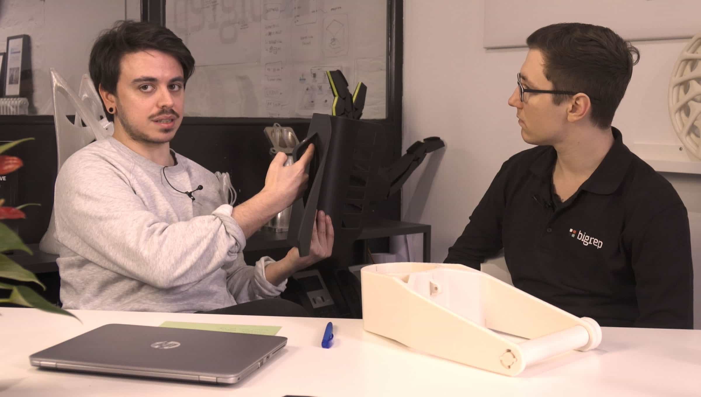
Take this hand jig designed by BigRep, for example. It’s an alignment tool for automotive manufacturing processes that doesn’t require significant force. Ordinarily, the handle for this kind of fixture would have three faces with the two that are protruding from the base at 90-degree angles. Since an especially firm grip isn’t required, we limited the handle to two faces and protruded them at 45-degree angles – an overhang angle favorable to most FFF materials. In doing this, we sacrificed some of the handle’s empty space but saved significantly on material – both in terms of support material and the part itself.
If such an acute angle won’t work for your design’s overhang, consider changing the material you use. While BigRep’s PLA and PRO HT both work best with 45-degree overhangs, our engineering-grade materials are often suitable for harsher angles - like HI TEMP which can effectively print overhangs at angles of up to 65-degrees.


Chamfering
Sometimes reducing the faces on your design isn’t possible, so you can always try chamfering between the overhang’s outmost edge and base object. A “chamfering” is the transitional edge between two sides of an object, usually a 45-degree angle between two right-angle surfaces. It’s an easy process that most CAD software provides automated tools to accomplish. By chamfering your design, you can remove sharp angled overhangs, reducing them to manageable angles that your printer and material process can handle.
Structural Support
If you can’t change the angles on your design, or need to apply more than one design strategy, you can forgo wasteful slicer-generated support structures and design them yourself. In our hand jig we added “fins” as structural supports for the overhangs needed to form a handle.
Support fins are thin overhang tracings used to reinforce your design. You can see in our hand jig that we completely outlined the gap for our handle – even on the object’s base – to ensure it prints successfully without adding support structures. Fins trade some of what would be empty space in your design, so it’s important to make sure that enough room is left for the part’s intended use, but can save lots of support material and serve to strengthen your part’s extremities.

Internal Channels
Small internal channels won’t usually need additional support since FFF printers can easily handle a circular gap. However, there are some use cases where internal channels are too large to print without added support – especially in industrial applications where air or liquid flow might be important to your design. In the unusual case that an internal channel requires supports, they can be very difficult to remove without a water-soluble support material used on a dual-extrusion 3D printer, if not impossible.
To solve this tricky problem, don’t limit yourself to circular internal channels. The common circular shape for internal channels seems like common sense, but it’s just one of those holdovers from traditional manufacturing when drilling was the easiest way to form a channel. To design for additive manufacturing, you can easily change your channel’s shape to print better. Usually a teardrop shape, with the point at the top, is preferred to keep all angles at 45-degrees and easily printable. Don’t limit yourself, though. If you’re still finding supports necessary in your internal channels take a closer look at the weak points and experiment with the channel’s shape to find one that suits your needs.
Conclusion
There are a lot of different ways you can optimize your designs to reduce or entirely remove support structures. By doing so, you can minimize post-processing, save material, and print your parts faster. Don’t be afraid to redesign features that we might take for granted. Remember that design lags behind production technology, so question the necessity of any inefficiencies in your designs and consider how they might be optimized with the advanced tools now at your disposal.
You can always find some inspiration by seeing how the experts tackle this change. Check out our free case study, How Airbus Manufactures Shipping Cases In-House with Large-Format Additive, to learn how Airbus, SAS reinvented shipping case design with additive manufacturing.
Find out how industry leaders are using BigRep 3D printers to create affordable and secure investment shipping containers on demand for sensitive aerospace equipment in our case study with Airbus:
Read Now