Ever wondered how top hydraulic engineers optimize river systems without real-world risks?
Step into the advanced hydraulics lab at Helmut Schmidt University. Here, Dr. Mario Oertel and his team are transforming weir designs with the BigRep ONE 3D printer, turning digital concepts into tangible prototypes swiftly.
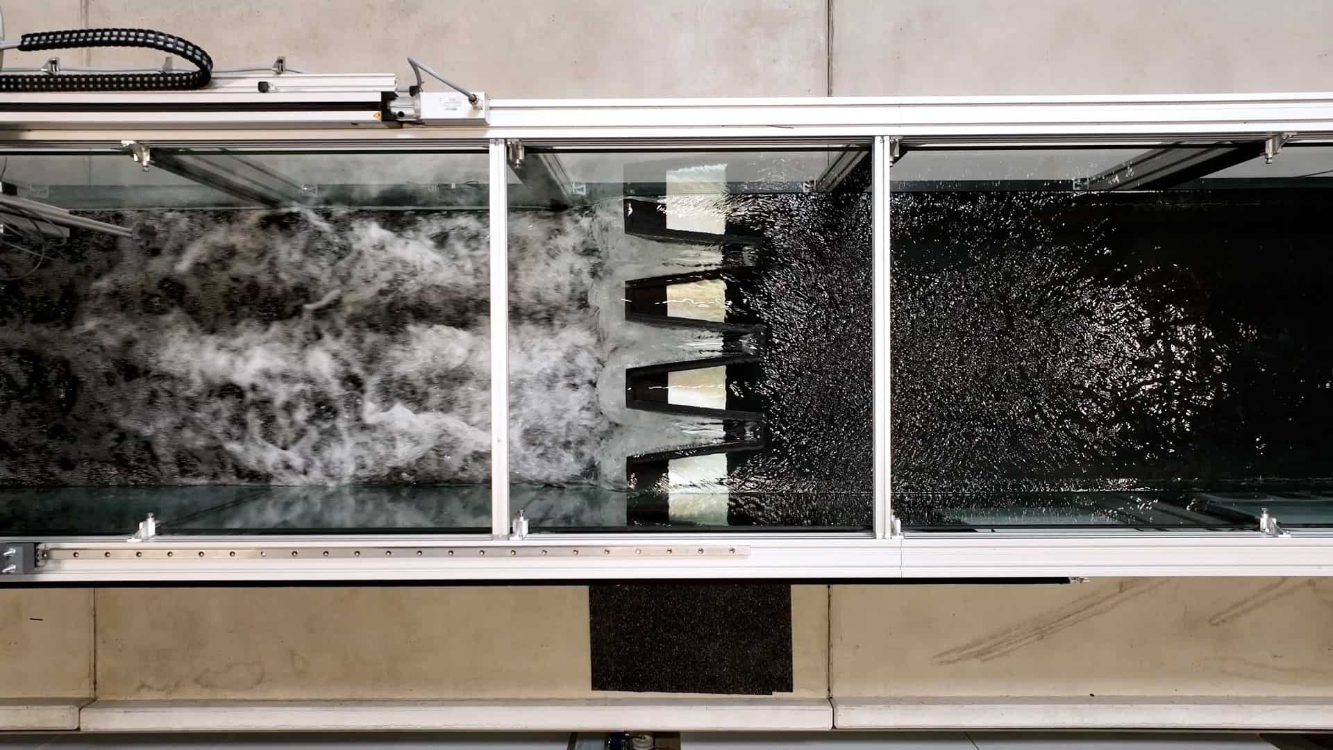
This fusion of time-honored hydraulic research and contemporary technology is redefining water management. The lab, discharging 1,500 liters per second through a scaled river model, goes beyond computer simulations to test and iterate weir designs, ensuring both precision and cost-efficiency.
Discover how this blend of traditional hydraulic research and modern tech is shaping the future of water management.
What is a Weir?
A weir is a lateral structure commonly used in open channel flow systems, such as rivers, streams, canals, and hydraulic laboratories, to measure and control the flow of water. It is a simple and versatile device that helps regulate water levels, monitor flow rates, and study fluid behavior. Weirs are designed to create a specific flow condition by constraining the water flow, causing it to spill over the top of the weir crest.
Weirs have a wide range of applications, including water level regulation, flood control, irrigation management, environmental monitoring, and hydraulic research. There are several types of weirs, each with different shapes and purposes. Common types include rectangular weirs, triangular weirs (V-notch weirs), trapezoidal weirs, and piano key weirs which are used in the hydraulics lab at the Helmut Schmidt University.

Digital Simulation vs Physical Experiments
Researchers and engineers at the Helmut Schmidt University conduct experiments and studies related to fluid mechanics, hydraulic systems, and fluid behavior as part of the civil engineering program. The hydraulics lab is equipped with various apparatus and instruments to investigate how fluids behave under different conditions, pressures, and flow rates. One focus of research is novel weir designs, which are tested in a river system scaled model: a one meter wide flume fitted with design prototypes.
By developing and testing new weir designs in the hydraulics lab, researchers can create more efficient weirs that can have a greater impact when integrated into river systems. Digital simulation is a powerful tool for researchers, but there are limits to what simulation alone can achieve. Using physical experiments with 3D-printed weirs offers several distinct advantages such as:
Real-world Validation:
Physical experiments provide direct validation of simulation results. Comparing actual measurements from the 3D-printed weir prototypes with simulated data helps validate the accuracy of the simulation model and the assumptions used.
Physical Interaction:
Researchers can observe the behavior of the flow, the water surface, and the interaction with the weir structure in real time. This hands-on experience provides valuable insights that might not be captured in simulations.
Fluid-Structure Interaction:
These experiments can capture intricate fluid-structure interactions, such as vortex shedding, eddies, and turbulence, which might be challenging to accurately simulate.
Unforeseen Phenomena:
Unexpected or complex phenomena may arise during physical experiments that were not anticipated in simulations. These phenomena can lead to new insights and discoveries.
Quantitative and Qualitative Data:
Offering a dual perspective, physical experiments churn out both quantitative (like flow rates and velocities) and qualitative data (visual observations), enriching the understanding of weir behavior.
Sensor Calibration and Verification:
To ensure accurate data collection, these experiments help to calibrate and verify measurement tools and sensors in the laboratory.Innovation and Optimization
Innovation and Optimization:
Physical experiments can spark innovation and lead to the discovery of new and optimized weir designs that might not have been considered in simulations alone.
Complex Geometries:
3D printing enables the creation of complex and customized weir geometries that may be challenging to simulate accurately. Physical prototypes can be designed and manufactured with greater freedom and creativity.

3D Printed Weirs for Hydraulics Research
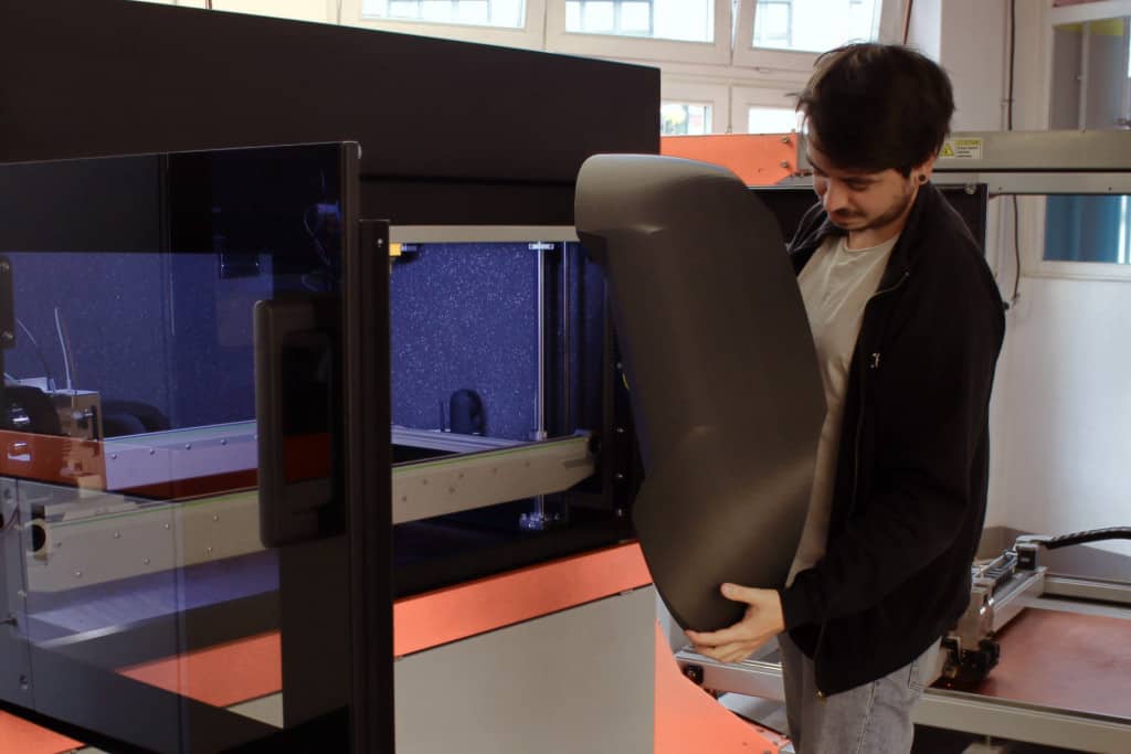
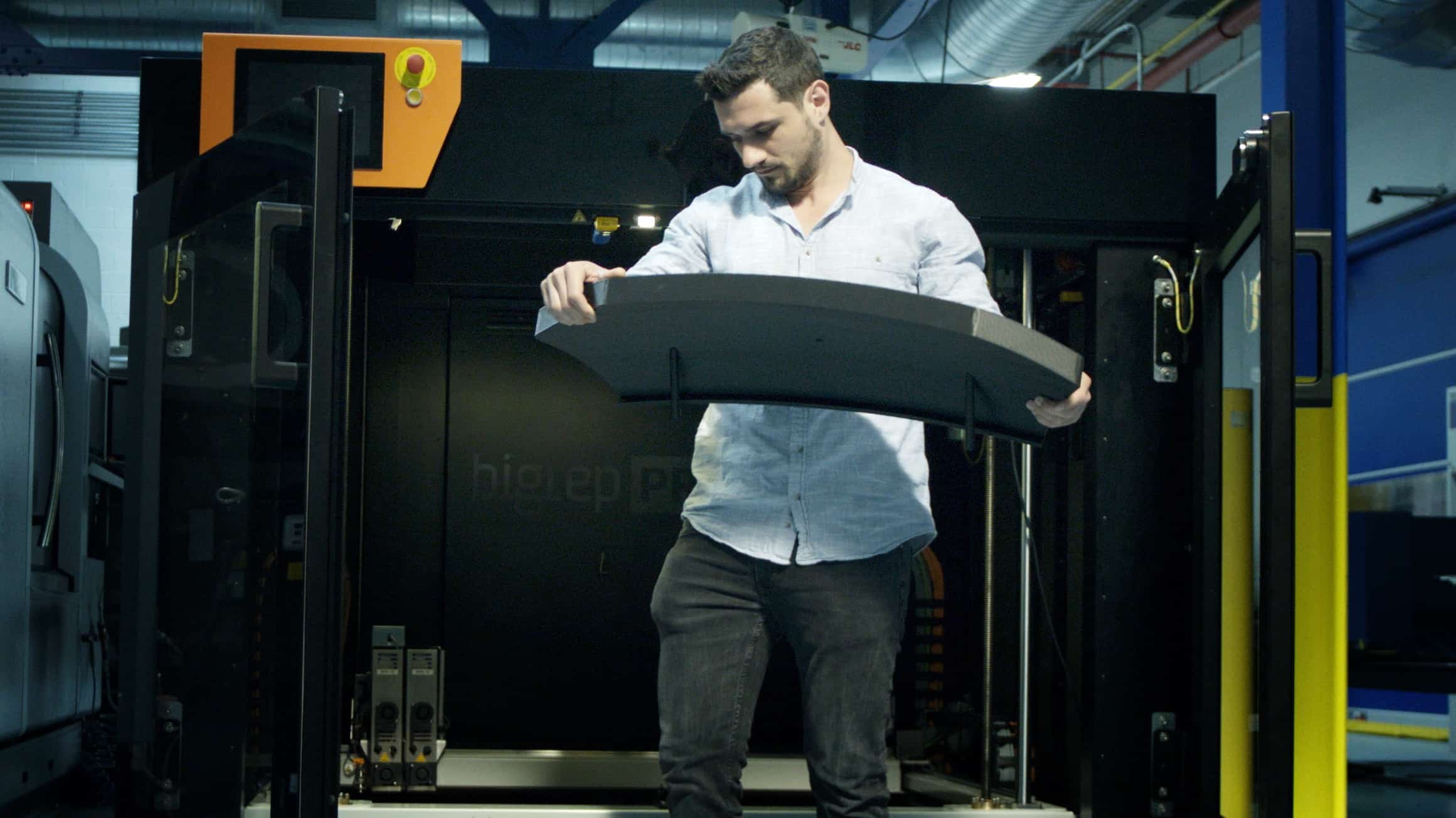
One project by the hydraulic engineering researchers at the Helmut Schmidt University focuses on piano key weirs, so named for their resemblance to the keys on a piano. Piano key weirs are designed to efficiently manage high flow rates and prevent flooding while taking up less space than conventional weirs. This makes them particularly useful in urban and confined environments.
While weir prototypes would traditionally be constructed from laser-cut acrylic glass that must be manually glued together, Dr. Mario Oertel turned to large-format 3D printing for a better solution. By 3D printing the weirs, researchers were able to quickly see their prototypes in action while cutting costs in the process. The BigRep ONE 3D printer also allowed them to easily iterate new designs and test them in the hydraulics lab within days.

Advantages of 3D Printing Weir Prototypes
Rapid Prototyping:
3D printing allows for quick and cost-effective production of weir prototypes. Researchers can design, iterate, and test multiple designs in a short period, speeding up the research and development process. Traditional manufacturing methods often involve longer lead times due to the need for tooling and setup. 3D printing minimizes lead times, enabling researchers to conduct experiments and gather data sooner.
Ease of Iteration:
Researchers can easily create custom weir designs tailored to specific objectives. This flexibility enables the exploration of various geometries, sizes, and configurations that might be challenging or expensive to achieve using traditional manufacturing methods. To test different parameters and variables, researchers can easily modify and print multiple iterations of weir prototypes. This iterative testing process can lead to more refined and optimized designs.
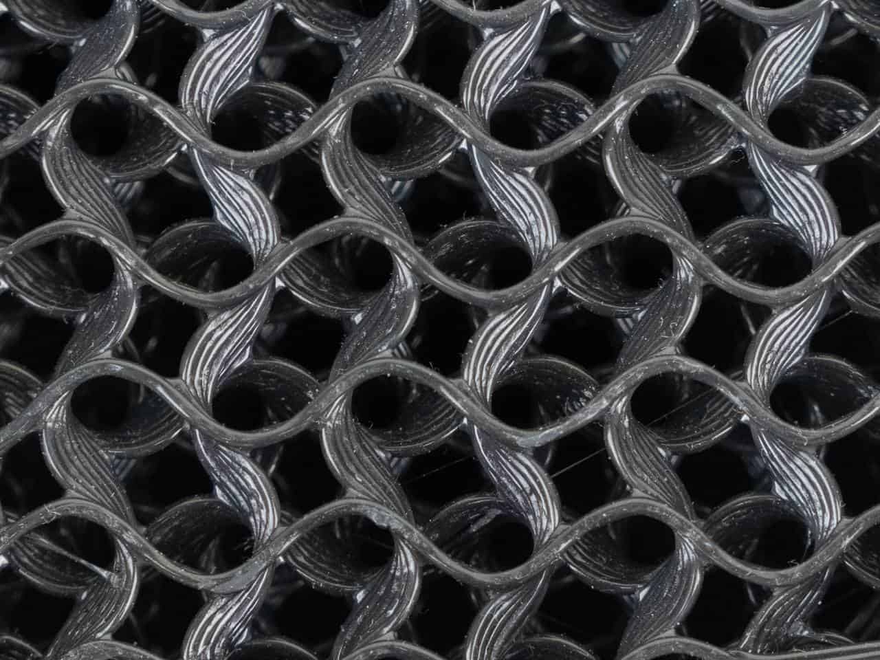
Complex Geometries:
3D printing enables the creation of intricate and complex geometries that may not be feasible with traditional machining methods. This is particularly useful for exploring novel weir shapes and designs.
Cost Savings:
Traditional machining methods can be expensive, especially for small-batch or one-off prototypes. 3D printing reduces material waste and production costs, making it more cost-effective for research purposes. After a slight learning curve, the researchers in the hydraulics lab were able to adjust slicing parameters in BigRep BLADE to reduce material usage by more than 60%.
Reduced Lead Time:
Traditional manufacturing methods often involve longer lead times due to the need for tooling and setup. Typical weir prototypes are constructed from acrylic glass, which is time consuming and expensive to produce. 3D printing minimizes lead times, enabling researchers to conduct experiments and gather data sooner.
Material Selection:
BigRep offers a wide range of filaments, plus BigRep 3D printers are open for third party filaments, allowing researchers to choose materials that balance research requirements with print quality and affordability. This is especially important in hydraulics research where accurate material properties can impact prototype behavior. Researchers at the Helmut Schmidt University hydraulics lab found great results printing weirs with BigRep PLX because it is easy to print, affordable, and produces beautiful surfaces.
Educational Tool:
3D-printed weir prototypes provide a tangible representation of theoretical concepts, making it easier for researchers and students to understand and visualize fluid flow patterns, velocity profiles, and other hydraulic phenomena. They can also be equipped with sensors and instrumentation to collect data during experiments. This data can be used for analysis, validation, and calibration of hydraulic models.

Large Format 3D Printing in Research Institutes
While the BigRep ONE is placed within the hydraulics lab of the Helmut Schmidt University, other departments and students can access the large-format 3D printer for additional research and projects. This facilitates collaborative projects involving students and faculty from different departments, encouraging interdisciplinary learning and problem-solving. Additionally, familiarity with large-format 3D printers equips students with skills and knowledge that are increasingly valuable in the many industries adopting additive manufacturing.
Having a large-format 3D printer in a university can enhance the learning experience, foster innovation, and prepare students for the evolving demands of modern industries. It serves as a versatile tool that encourages creativity, problem-solving, and collaboration across various academic disciplines.

LARGE-SCALE INNOVATION. LIMITLESS CREATIVITY.
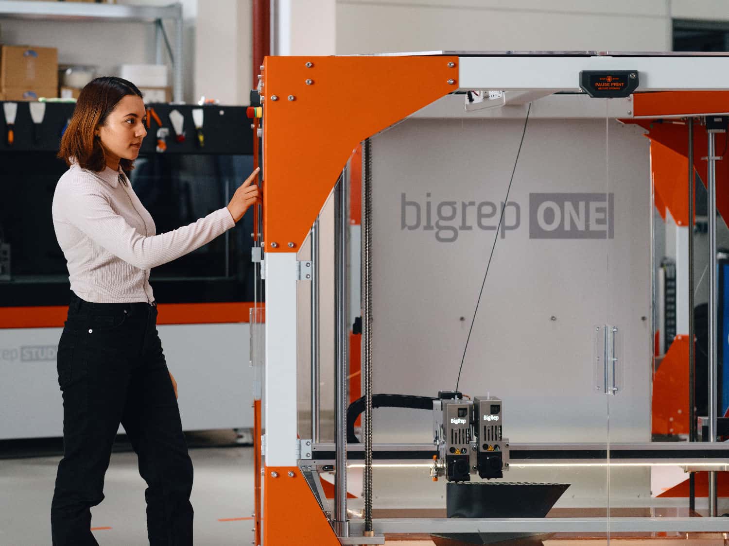
The BigRep ONE is an award-winning, large-format 3D printer at an accessible price point. With over 500 systems installed worldwide, it's a trusted tool of designers, innovators, and manufacturers alike. With a massive one-cubic-meter build volume, the fast and reliable ONE brings your designs to life in full scale.

LARGE-SCALE INNOVATION. LIMITLESS CREATIVITY.
The BigRep ONE is an award-winning, large-format 3D printer at an accessible price point. With over 500 systems installed worldwide, it's a trusted tool of designers, innovators, and manufacturers alike. With a massive one-cubic-meter build volume, the fast and reliable ONE brings your designs to life in full scale.
About the author:


")

")